Coriolis Mass Flow Meter

a mass flow meter and coriolis technology, applied in the field of can solve the problems of affecting the measurement, affecting the accuracy of measurement, and the desire for smaller coriolis mass flow meter, and achieves the effect of simple construction of vibration pickups and favorable effect on the robustness of vibration pickups

Inactive Publication Date: 2012-07-26
SIEMENS AG
View PDF16 Cites 7 Cited by
  • Summary
  • Abstract
  • Description
  • Claims
  • Application Information

AI Technical Summary

Benefits of technology

[0014]In comparison with the conventional practice of providing a Coriolis mass flow meter with plunger coils as vibration pickups, the optical vibration pickups in accordance with the invention have the advantage that they are much less sensitive to external electromagnetic interferences and that they have a greater sensitivity with respect to the deflection of the measuring tube. This is because, on account of the changing of the light intensity with a variable frequency that is dependent on the velocity of the tube at a particular time and is on average much higher than the frequency of the vibrations of the at least one measuring tube, a higher resolution is achieved with respect to the position of the measuring tube, and consequently with respect to the phase position of the measuring tube vibration. The Coriolis mass flow meter in accordance with the invention also responds quickly to changes in the mass flow, and current measured values can be determined more quickly. This is of particular advantage in the case of highly dynamic metering operations, in which the mass flow can change very quickly. A further advantage can be seen in an improvement in the signal-to-noise ratio with respect to low-frequency process vibrations that can be coupled into the meter via pipelines, due to the use of a measuring signal of higher frequency.
[0015]Since a contactless measuring method is involved, no wires or lines that could influence the vibrations of the measuring tube or become detached from it over a prolonged operating time have to be secured to the tube. The optical grid that is coupled to the at least one measuring tube can be realized with a very small dead weight, so that its effects on the vibrational properties of the measuring tube are minimal. It is also advantageous that the optical vibration pickups can be realized with a comparatively small type of construction, and consequently can also be used in Coriolis mass flow meters with a small housing. In particular, no attachments of any great size are required on the measuring tube. On account of the improved resolution of the vibration pickups, a phase difference can be detected even with relatively small vibrational amplitudes. It is therefore possible to operate the Coriolis mass flow meter with a smaller vibrational amplitude, and consequently to reduce the power consumption of the excitation system.
[0016]A particularly clear change in intensity in the case of vibrations, and consequently a good signal quality of the luminous flux passing through the grids, can be achieved if devices for limiting the expansion of the beam are provided upstream of the pair of superjacent grids. In this way, a luminous flux with little expansion of the beam can be directed substantially perpendicularly onto the superjacent grids.
[0017]An embodiment which has proven to be particularly advantageous is one in which the superjacent grids are realized by two optical line grids aligned substantially parallel to one another. With lines running perpendicularly to the direction of vibration of the at least one measuring tube, clear fluctuations in the brightness of the transmitted light can be detected. Brightness modulations occur as a moire effect, for example, when the grid constants of the optical line grids deviate minimally from one another or if line grids that have the same grid constant but are turned slightly with respect to one another are used. Consequently, in this case the displacement of the grids in relation to one another can also be determined with greater accuracy.
[0019]For directing the light to the superjacent grids and for recording the luminous flux transmitted through the grids, light-conducting fibers may be used in the optical vibration pickups. It is thereby possible to advantageously operate two or more optical vibration pickups with a single light source. Furthermore, this has the advantage that the light source and the light receiver, which represent comparatively sensitive components, can be arranged at a greater distance from the measuring tube. In particular, when the mass flow meter is used with hot process media, this has an advantageous effect on the robustness of the vibration pickups. When light-conducting fibers are used, it is possible to dispense with the aperture diaphragm upstream of the superjacent grids, because the light-exiting cross section of the fibers is already comparatively small.
[0021]When using at least one pair of measuring tubes arranged substantially parallel to one another that vibrate with a phase position offset by 180° with respect to one another for mass equalization, a particularly simple construction of the vibration pickups is obtained, however, if the other grid, respectively, of the pairs of superjacent grids is secured to the other measuring tube, respectively, of the pair of measuring tubes arranged parallel to one another. This makes it possible for the conventional vibration pickups which, for example, operate with the known magnetic plunger coils, to be simply substituted by the novel optical vibration pickups. Such an embodiment is particularly simple.

Problems solved by technology

Particularly in an aggressive environment, electromagnetic interference fields may falsify the measuring signal and thereby influence the measurement.
Interferences superposed on the measuring signals make it more difficult to calculate accurate measured values.
A further problem is the desire for smaller Coriolis mass flow meters.

Method used


Image

  • Coriolis Mass Flow Meter
  • Coriolis Mass Flow Meter
  • Coriolis Mass Flow Meter

Examples


Embodiment Construction

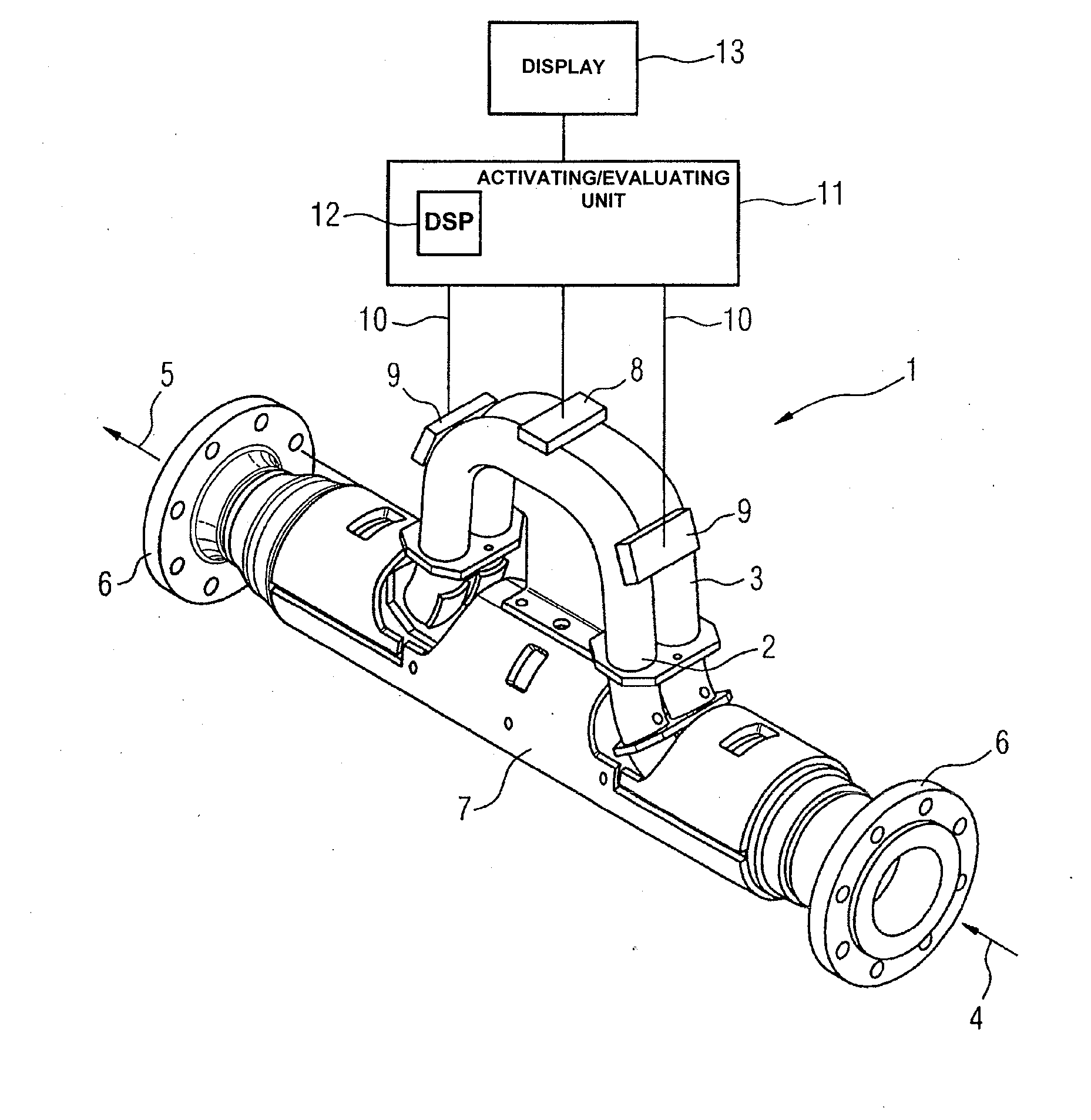
[0027]FIG. 1 shows a Coriolis mass flow meter 1 according to a preferred exemplary embodiment of the present invention. The mass flow meter 1 has a first measuring tube 2 and a second measuring tube 3, which are arranged substantially parallel to one another. These are usually made from one piece by bending. The path followed by the measuring tubes 2 and 3 is substantially U-shaped. A flowable medium flows according to an arrow 4 into the mass flow meter 1, and thereby into the two inlet portions of the measuring tubes 2 and 3 located downstream of an inlet splitter, which cannot be seen in FIG. 1, and according to an arrow 5 out again from the outlet portions and the outlet splitter located downstream thereof, which likewise cannot be seen in FIG. 1. Flanges 6, which are fixedly connected to the inlet splitter and the outlet splitter, serve for securing the mass flow meter 1 in a pipeline not represented in FIG. 1. The geometry of the measuring tubes 2 and 3 is kept largely constan...


PUM


Abstract

A Coriolis mass flow measuring device, comprising at least one measurement pipe, through which a medium flows and which is induced to vibrate by an exciter arrangement, wherein two optical vibration sensors, arranged before and after the exciter arrangement in the longitudinal direction of the at least one measurement pipe, provide vibration signals, based on which an activation and evaluation device determines the mass flow and / or the density of the medium. The optical vibration sensors each have a pair of superimposed grids having periodic structures to improve the resolution that can be achieved by the optical vibration sensors.

Description

CROSS-REFERENCE TO RELATED APPLICATIONS[0001]This is a U.S. national stage of application No. PCT / EP2009 / 005829 filed 11 Aug. 2009.BACKGROUND OF THE INVENTION[0002]1. Field of the Invention[0003]The present invention relates to a Coriolis mass flow meter with at least one measuring tube, which is flowed through by a medium and such mass flow meters which can particularly be used in as field devices for process instrumentation;[0004]2. Description of the Related Art[0005]In process engineering installations, a variety of field devices for the process instrumentation are used to control processes. Measuring transducers serve for recording process variables, such as the temperature, pressure, filling level, mass flow, density or gas concentration of a medium. Final control elements allow the process sequence to be influenced in accordance with recorded process variables based on a strategy that is, for example, prescribed by a control station. A control valve, a heater or a pump may be...

Claims


Application Information

Patent Timeline
Patent Type & Authority Applications(United States)
IPC IPC(8): G01F1/84
CPCG01F1/8477G01F1/8427
Inventor EGNER, DANIELSCHORB, HERBERTVON DOSKY, STEFAN
Owner SIEMENS AG
Why Eureka
Try Eureka