Ice-making mechanism of ice-making machine

Inactive Publication Date: 2006-03-14
HOSHIZAKI ELECTRIC CO LTD
View PDF18 Cites 23 Cited by
  • Summary
  • Abstract
  • Description
  • Claims
  • Application Information

AI Technical Summary

Benefits of technology

[0011]In view of the foregoing problems inherent in the ice-making mechanisms of ice-making machines according to conventional technology, the present invention was proposed to solve the problems appropriately and an object of the invention is to provide an ice-making mechanism of an ice-making machine, capable of achieving the improvement of ice-making efficiency, based on the suppression of increases in concentrations of the impurities contained in ice-making water.

Problems solved by technology

In the closed-cell or open-cell type of ice-making mechanism 10 or 11, respectively, if concentrations of the impurities contained in the ice-making water stored within the ice-making water tank 20 increase too significantly, this may cause the problems that masses of ice become clouded to deteriorate in appearance or become fused too early or that the masses of ice inside the ice storage compartment easily stick to one another.
In such a case, the ice-making water that was cooled during the previous ice-making operation cannot be effectively used, which causes a great loss of energy.
In addition, since the temperature of the ice-making water stored within the ice-making water tank 20 reaches ordinary temperature, the problem is pointed out that the time to cool the great amount of ice-making water within the ice-making tank 20 in next ice-making operation is required, so that a longer ice-making cycle is caused to invited a deterioration of ice-making efficiency.

Method used


Image

  • Ice-making mechanism of ice-making machine
  • Ice-making mechanism of ice-making machine
  • Ice-making mechanism of ice-making machine

Examples


embodiment 1

[Operation of Embodiment 1]

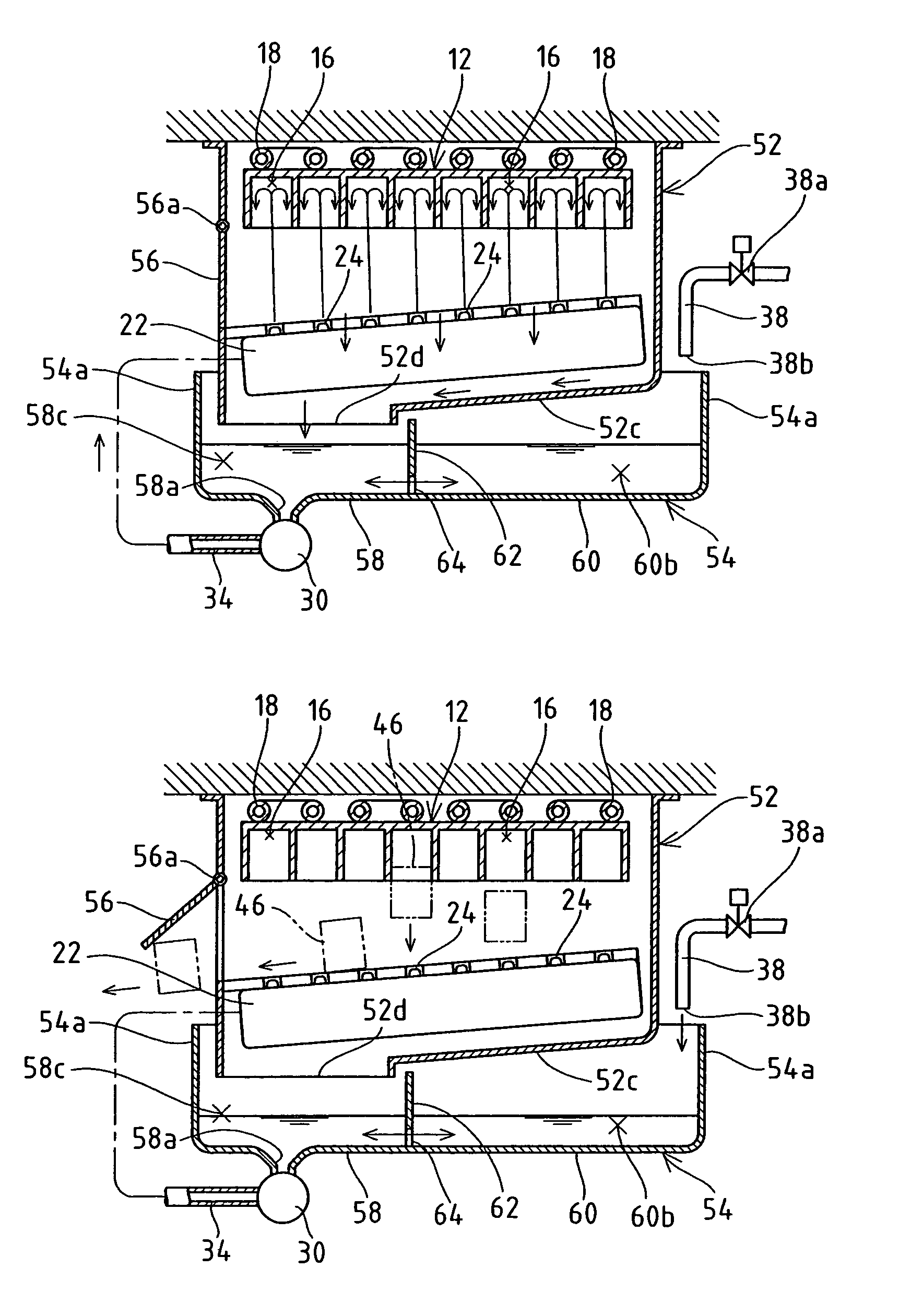
[0037]The operation of the ice-making mechanism of an ice-making machine in Embodiment 1 is described below. First, an ice-making process by the ice-making mechanism in Embodiment 1 is briefly described using FIG. 3. When ice-making operation is started, a refrigerant circulates through the evaporation pipe 18 and the ice-making compartments 16 are force-cooled. Also, the ice-making water in the ice-making water tank 54 is pressure-fed to the water tray 22 by the pump motor 30 and spray-supplied to each ice-making compartment 16 via each water-spraying hole 24. The water is cooled on inner wall surfaces of the ice-making compartments 16 and begins to freeze in a laminar form. As shown in FIG. 3(a), un-iced water that has not become iced flows downward through the return hole of the water tray 22, then drips onto the guide 52c of the mechanical base 52 that is positioned below the guide 52c, and is dropwise collected from the opening 52d into the circulatin...

embodiment 2

[Operation of Embodiment 2]

[0063]Next, the operation of the ice-making mechanism of an ice-making machine in Embodiment 2 is described below. First, an ice-making process by the ice-making mechanism in Embodiment 2 is briefly described using FIG. 5 or 6. During ice-making operation, the water tray 22 and ice-making water tank 82 in the above-mentioned ice-making mechanism close the ice-making compartments 16 from below and are positioned horizontally and each water-spraying hole 24 faces an associated ice-making compartment 16. When ice-making operation is started, a refrigerant circulates into the evaporation pipe 18 and the ice-making compartments 16 are force-cooled. Also, the ice-making water in the ice-making water tank 82 is pressure-fed to the water tray 22 by the pump motor 30 and after being spray-supplied to each ice-making compartment 16 via each water-spraying hole 24 to start icing in a laminar form. Un-iced water, i.e., water that has not become iced after being spraye...

modification examples

[Modification Examples]

[0071]Provided that the guide described above is adapted so as to accept the un-iced water dripping from the water tray 22 and guide the dripping un-iced water to the circulating tank section and in order for no such water to flow directly into the retention tank section, it is likewise possible to employ the construction in which the guide has a smooth and flat surface, or the construction in which the guide is fixed. In addition, in terms of the relationship in position between the circulating tank section 84 and retention tank section 86 in Embodiment 2, both tank sections are formed in parallel to a direction orthogonal to the axial direction of the support axis 23 by being separated by the partition plate 88 extending in the axial direction of the support axis 23. However, a partition plate extending in a direction orthogonal to the axial direction of the support axis 23 may be used to separate the above two tank sections so as to make both parallel to th...


PUM


Abstract

An ice-making water tank 54 capable of improving ice-making efficiency by suppressing increases in concentrations of the impurities contained in ice-making water is divided into a circulating tank section 58 and a retention tank section 60 by a partition plate 62. The ice-making water stored within the circulating tank section 58 and the ice-making water stored within the retention tank section 60 are made movable between each other by a communication hole 64. A capacity of the retention tank section 60 is set to have a capacity greater than that of the circulating tank section 58. Above the retention tank section 60 is covered with a guide 52c of a mechanical base 52, and the un-iced water cooled during ice-making operation is collected only into the circulating tank section 58 via an opening 52d opening downward above the circulating tank section 58.

Description

FIELD OF THE INVENTION[0001]The present invention relates to an ice-making mechanism of an ice-making machine, and more particularly, to an ice-making mechanism of an ice-making machine which spray-supplies ice-making water upwards to a plurality of ice-making compartments opening downward, for example, and thus continuously manufactures ice cubes (masses of ice).DESCRIPTION OF THE RELATED ART[0002]Spray-type automatic ice-making machines that spray-supply ice-making water from an upward direction to a plurality of ice-making compartments opening downward and thus continuously manufacture ice cubes (masses of ice) are conveniently used in the kitchens of coffee shops, restaurant, and other facilities. As shown in FIG. 10, the ice-making mechanisms of such spray-type automatic ice-making machines include a so-called closed-cell type of ice-making mechanism 10 (refer to, for example, Japanese Unexamined Utility Model Registration Publication No. Hei 6-28568). This ice-making mechanism...

Claims


Application Information

Patent Timeline
IPC IPC(8): F25C1/12F25C1/22F25C1/04
CPCF25C1/045F25C2500/08F25C2400/14
Inventor ISHITOMI, KUNIHIKOKAWASUMI, MASAAKITAKAHASHI, KENJIKADOWAKI, SHIZUMANAGASAWA, SHINICHIHOSOGI, TADAHARU
Owner HOSHIZAKI ELECTRIC CO LTD
Why Eureka
Try Eureka