Ejector pump liquid feeding vertical cylinder type ice-making machine

A technology of ejector pump and ice maker, which is applied to ice making, ice making, lighting and heating equipment, etc., can solve the problems of low ice making capacity, high operating cost, low evaporative heat transfer efficiency of ice cylinder, etc. The effect of improving ice-making capacity, reducing energy consumption and improving ice-making efficiency

Active Publication Date: 2007-09-26
SIFANG TECH GRP CO LTD
View PDF0 Cites 5 Cited by
  • Summary
  • Abstract
  • Description
  • Claims
  • Application Information

AI Technical Summary

Problems solved by technology

The thermal expansion valve is used for liquid supply, and the evaporative heat transfer efficiency of the freezing cylinder is low, and the ice making capacity is low; the refrigerant pow

Method used


Image

  • Ejector pump liquid feeding vertical cylinder type ice-making machine
  • Ejector pump liquid feeding vertical cylinder type ice-making machine
  • Ejector pump liquid feeding vertical cylinder type ice-making machine

Examples


Embodiment 1

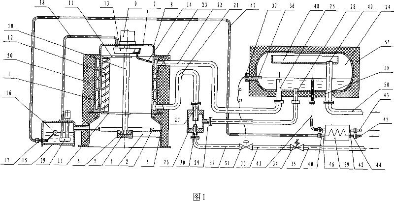
[0020] Ejector pump liquid supply vertical cylinder ice machine (see Figure 1), including a vertical cylindrical jacket type refrigeration evaporation icing cylinder 1, below the icing cylinder 1 there is a cylindrical base 3 with an annular water collection tank 2, In the center of the cylindrical base 3, there is a bearing seat 5 connected with the support rod 4 and the cylindrical base 3. There is a bearing 6 in the bearing seat 5. There is an end cover 8 with an observation window 7 on the icing cylinder 1, and the observation window may not be provided. , the end cover 8 is equipped with an electric reducer 9, and the center of the icing cylinder 1 has a rotary main shaft 10 whose lower end is supported by a bearing 6 and whose upper end is connected to the output shaft of the electric reducer 9. There is a cantilever 11 on the rotary main shaft 10, and a cantilever 11 is installed at one end. The ice scraper 12, the water spray pipe 14 for spraying freezing water to the i...

Embodiment 2

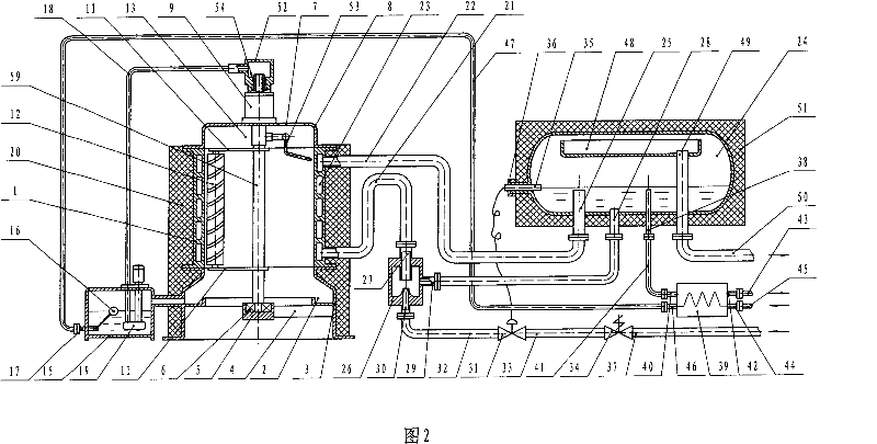
[0030] The difference from Embodiment 1 is: the water pump 19 is connected with the sealing joint 52 on the upper end of the rotary main shaft 59 with the water injection pipe 18 (see Figure 2), the sealing joint 52 is sealed with the rotary main shaft 59, and the joint between the rotary main shaft 59 and the water spray pipe 53 is The upward part is a hollow structure, 54 is a dynamic sealing ring, and the upper end of the rotary main shaft 59 can rotate in the sealing ring 54 .

Embodiment 3

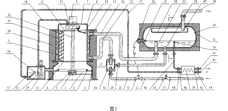
[0032] The difference from Embodiment 1 or 2 is: the air inlet of the horizontal low-pressure circulation barrel 24 back air outlet pipe 49 extends from the barrel wall of the horizontal low-pressure circulation barrel 24 on the upper part of the gas collection long disk 48 into the gas collection long disk 48 Inside, the air outlet of the horizontal low-pressure circulation barrel 24 return air outlet pipe 49 passes through the barrel wall on the top of the low-pressure circulation barrel 24 and links to each other with the suction pipe 50 of the refrigeration compressor unit (seeing Fig. 3, 4).


PUM


Abstract

It relates to a cylindrical ice making machine that comprises the vertical cylindrical clamping cooling steam icing barrel, cylindrical base with ring shape water accumulation slot, center of the cylindrical base having bearing base and bearing, end cover on the icing barrel, electric decelerator on the end cover, center of the icing barrel having electric decelerating drive main return shaft that have ice scraper and showering pipe, water tank connected to the ring water accumulation slot, water level controller on the water tank, inlet pipe and water pump, icing barrel having cooling agent inlet pipe and outlet pipe, icing barrel connecting with horizontal low pressure circulating barrel, ejection pump, horizontal low pressure circulating barrel and water tank connected with the heat exchanger respectively, and the insulation protective layer outside the icing barrel and horizontal low pressure circulating barrel. It has strong icing ability, with economical and reliable running.

Description

Technical field: [0001] The invention relates to a vertical cylinder ice maker. Background technique: [0002] Existing vertical cylinder ice machines use a thermal expansion valve for liquid supply or a refrigerant power pump for circulating liquid. The thermal expansion valve is used for liquid supply, and the evaporative heat transfer efficiency of the freezing cylinder is low, and the ice making capacity is low; the refrigerant power pump is used for circulating liquid supply, and the power consumption is high, and the moving parts of the pump are worn, the failure rate is high, and the operating cost is high. high. Invention content: [0003] The object of the present invention is to provide a technical scheme of a vertical cylinder ice machine with ejector pump for liquid supply. The icing cylinder of the machine has high evaporation and heat transfer efficiency and strong ice making ability, which is beneficial to reduce power consumption; Economical, reliable and...

Claims


Application Information

Patent Timeline
IPC IPC(8): F25C1/12
Inventor 钱洪黄杰
Owner SIFANG TECH GRP CO LTD
Why Eureka
Try Eureka