Ice maker and refrigerator

A technology for ice machines and ice trays, which is applied in ice making, ice making, household refrigeration devices, etc. It can solve problems such as unsatisfactory use requirements, reduced utilization of cold air, and reduced air volume of ice trays, so as to improve ice production. Effect, efficiency improvement, effect of shortening ice making cycle

Active Publication Date: 2016-03-23
HEFEI HUALING CO LTD +1
View PDF5 Cites 5 Cited by
  • Summary
  • Abstract
  • Description
  • Claims
  • Application Information

AI Technical Summary

Problems solved by technology

[0005] The technical problem to be solved by the present invention is: in order to solve the problem that there are many obstacles between the air inlet of the existing ice maker and the ice-making tray, this will form wind resistance, resulting in a decrease in the overall air volume supplied to the ice-making tray, and the use of cold wind The rate is greatly reduced, which makes the water in the ice-making tray slow down to form ice cubes, and the ice-making efficiency is low, which cannot meet the needs of use.

Method used


Image

  • Ice maker and refrigerator
  • Ice maker and refrigerator
  • Ice maker and refrigerator

Examples


Embodiment 1

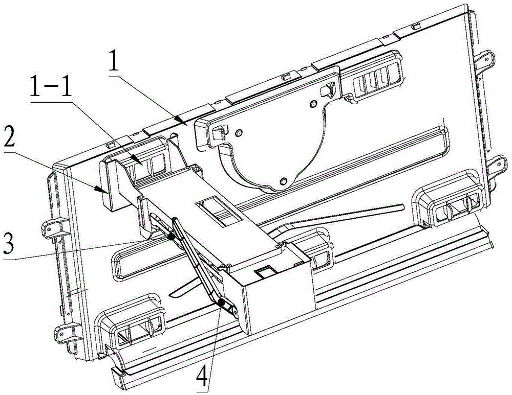
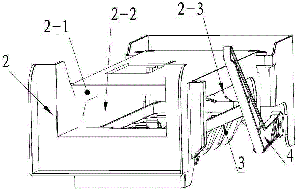
[0028] The bracket 2 is the installation and fixing base of the whole ice maker, and is mainly used for installing the ice-discharging motor 5, the ice-making tray 3 and forming a cavity, and the cavity is used for accommodating the ice-making tray 3 and for cooling air circulation. The lower edge of the air inlet is opposite to the upper surface of the ice-making tray 3. The cold air enters from the air inlet and passes through the upper surface of the ice-making tray 3. After completing the heat exchange, it is directly discharged from the air outlet. The air inlet and the ice-making tray 3, there is no obstacle between them, and there is no obstruction during the flow of cold air. From the entrance of the air inlet to the ice-making tray 3, the flow direction of the cold air in the horizontal direction remains unchanged. There is almost no loss of air volume; this structure can maximize the use of the air volume entering the air inlet, the amount of cold air passing through ...

Embodiment 2

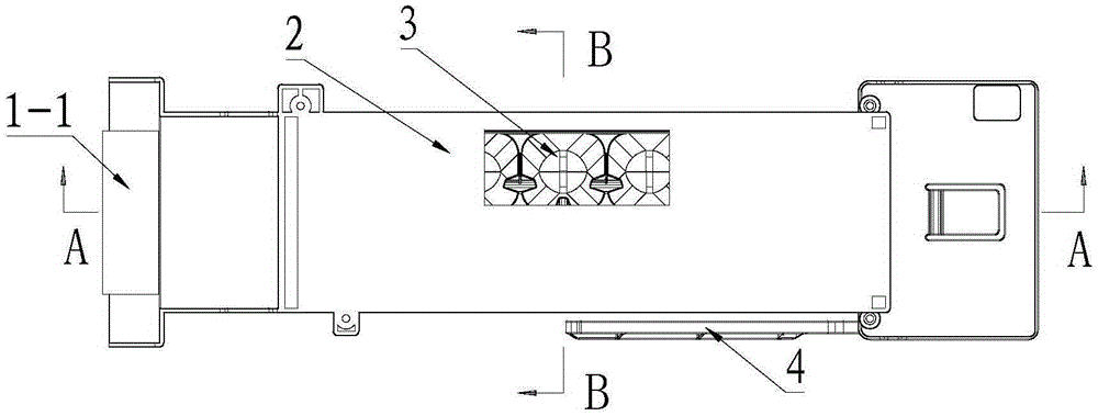
[0039] preferred, such as image 3 As shown, the ice machine can add water through the window opened on the top plate, and the water inlet pipe passes through the top of the storage room to add water to the ice-making tray 3 through the window. After the ice machine is installed, the window is blocked by the top of the storage room , forming a closed structure; only the end of the water inlet pipe protrudes, which will not affect the flow of cold air, and is conducive to the circulation of cold air.

[0040] Further, the storage room is a freezer room. The low-temperature environment of the freezer is conducive to further improving the ice-making efficiency.

[0041] The structure designed by the present invention can maximize the use of the air volume at the air outlet because there are no obstacles between the air outlet and the ice-making tray 3. At the same time, there are no obstacles on both sides of the ice-making tray 3, and the speed of the wind passing by It is als...


PUM


Abstract

The invention belongs to the technical field of refrigerator ice making, and discloses an ice maker and a refrigerator. The ice maker comprises a bracket, ice making cells and an ice discharge motor; the ice discharge motor is mounted on the bracket; the ice making cells are in drive connection with the ice discharge motor; a cavity is formed in the bracket; the ice making cells are positioned in the cavity; an air inlet and at least one air outlet are formed in the side wall of the bracket; and the air inlet is used for leading cold air to pass through the upper surfaces of the ice making cells. Compared with the prior art, the ice maker has the following prominent improvements: (1) more ice blocks can be made under the same conditions, so that the ice making quantity in unit time is large; (2) the frost blockage condition cannot be generated under the same conditions; and (3) the ice making cost is lower under the same ice making technical scheme conditions.

Description

technical field [0001] The invention relates to the technical field of refrigerator ice making, in particular to an ice maker and a refrigerator. Background technique [0002] The existing Chinese patent 201120468430.8 discloses an ice maker for a refrigerator. The ice maker includes a hanger, a drive motor, an ice probe, an ice tray, and an air duct formed by a cavity in the hanger. Wherein the air duct is provided with an air inlet and an air outlet, and is also provided with a baffle for guiding the cold air to the ice-making tray. The cold air enters the air duct from the air inlet, and is guided by the baffle and blows from the air outlet to the ice tray. [0003] In this scheme, the cold air needs to pass through the air inlet, the air duct, the baffle, and the air outlet to blow to the ice tray, especially the setting of the baffle, so that there are many obstacles between the air inlet and the ice tray. This will form wind resistance, reduce the overall air volume ...

Claims


Application Information

Patent Timeline
Patent Type & Authority Applications(China)
IPC IPC(8): F25D23/12F25C1/04
CPCF25C1/04F25D23/12
Inventor 邵阳金湘彧吕正光
Owner HEFEI HUALING CO LTD
Why Eureka
Try Eureka