
Latch for section doors and the like, and operating sets including said latch

a technology for latches and section doors, applied can solve the problems of difficult embodied, difficult operation, and inability to be used in the field of latches,

Inactive Publication Date: 2006-03-14
FINARDI IVO
View PDF36 Cites 22 Cited by
  • Summary
  • Abstract
  • Description
  • Claims
  • Application Information

AI Technical Summary

Benefits of technology

"The present invention aims to improve latches for section doors by providing an arrangement that does not require a longer stroke than usual for a latch. The latch can automatically close without needing a handle lock, and it can be operated by a handle lock of any commercial construction. The latch is located coaxially with a small wheel that rolls within the side guide bars of the section door, so it does not interfere with the movement of the guide bars. The latch is guided to slide within a hollow pivot or axle, and it can be mounted on the section door or its hinges. The latch can also be provided with a spring that allows for an automatic closure when the section door reaches its closure position. The invention provides an improved arrangement for section doors that is convenient, practical, and does not require complicated or costly arrangements."

Problems solved by technology

The section doors suffer a serious problem with reference to the latches.
Therefore, when the latch is operated manually, the user should take care of operating the latch along its entire, unusually long stroke because, if inadvertently he opens the latch only in part, then a clamping or even a serious damage of the section door takes place during the door opening.
On the other hand if, as it often happens, the latch is operated by a handle lock, it is necessary to use a handle mechanism having features suitable to cover a long stroke, but such features are unusual for such mechanisms and, moreover, they are difficult to be embodied and are not of handy maneuver.
Operating such a long latch stroke through a limited rotation angle of a handle would be of difficult realization and, in any event, would require an excessive effort.
Such maneuver is uncomfortable, but in addition thereto it involves the danger that the user inadvertently omits the second part of the stroke whereby the latches, abandoned at a half of their stroke, come then to interfere with the guide bars in correspondence of the curved connection branches, thus causing the clamping or a serious damage of the section door.
An attempt has been made to make up for this dangerous disadvantage by submitting the handle to the action of a strong return spring, which impedes to abandon the handle in an intermediate position.
However, in this case the maneuver of the handle should overcome, in addition to the resistance of the latch movement, the force of the spring, whereby the maneuver involves an excessive effort and is very uncomfortable.
Another disadvantage shown by the section doors is that it is very difficult to provide an automatic closure of the latches when the closure position is attained by the section door; this effect may be obtained only at the cost of serious constructive complications.

Method used


Image

  • Latch for section doors and the like, and operating sets including said latch
  • Latch for section doors and the like, and operating sets including said latch
  • Latch for section doors and the like, and operating sets including said latch

Examples


Embodiment Construction

[0027]With reference to FIG. 3, in the following will be clarified the main problem, already mentioned in the preamble, that is noticed in the section doors with respect to the latch. A section door, of which only a portion is diagrammatically represented in profile in FIG. 3, comprises two side guide bars, only one of which is shown and includes a vertical branch G1, defining the operative position of the section door when closed, a upper horizontal branch G2, defining a disappearance position of the section door when open, and a curved connection branch G3, located between said vertical branch G1 and said upper horizontal branch G2. A number of section door elements E1, E2, E3, E4 are mutually connected by means of hinges C1, C2, C3, and they are provided at their end portions, near the hinges, with small running wheels R1, R2, R3 engaged in the side guide bars. The shape in cross section of a guide bar G1 and the engagement therein of a small running wheel R1 are diagrammatically...


PUM


Abstract

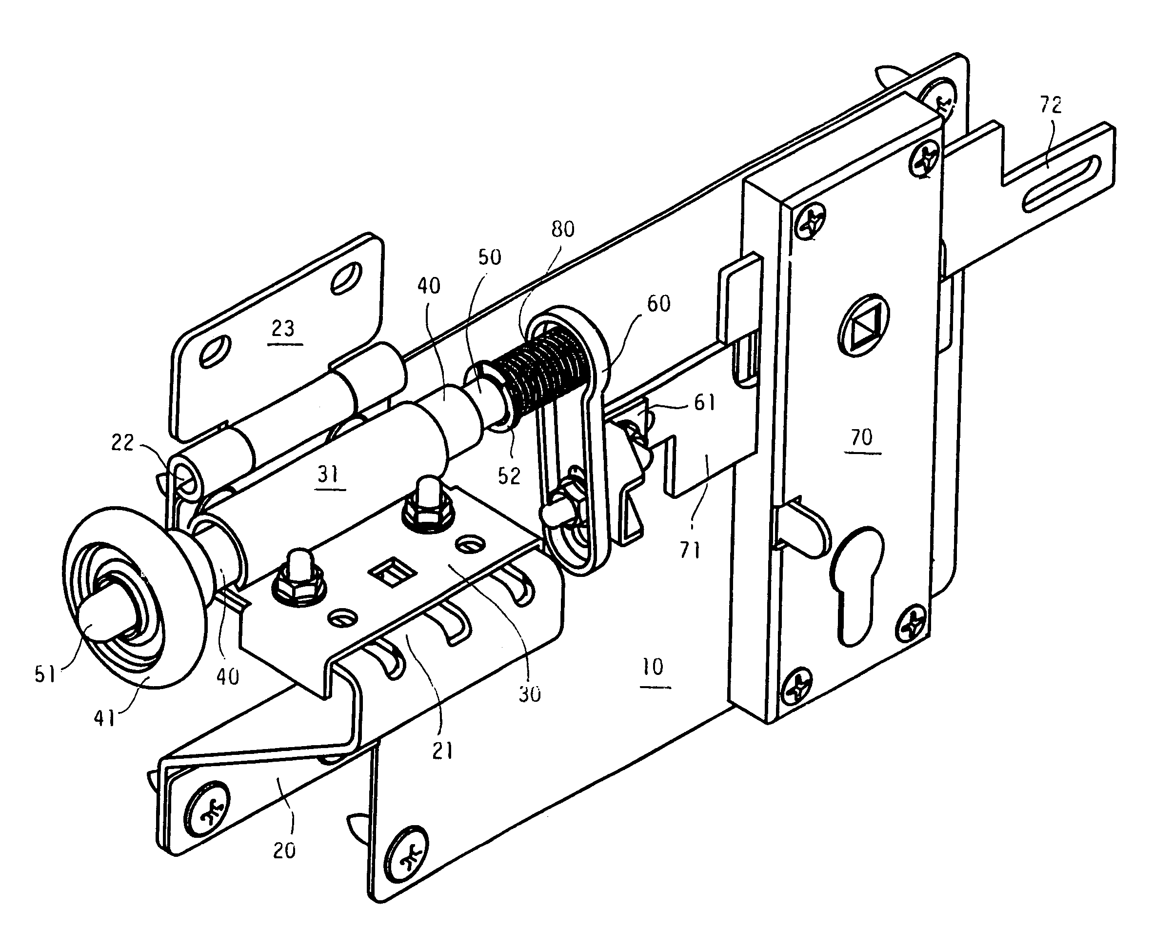
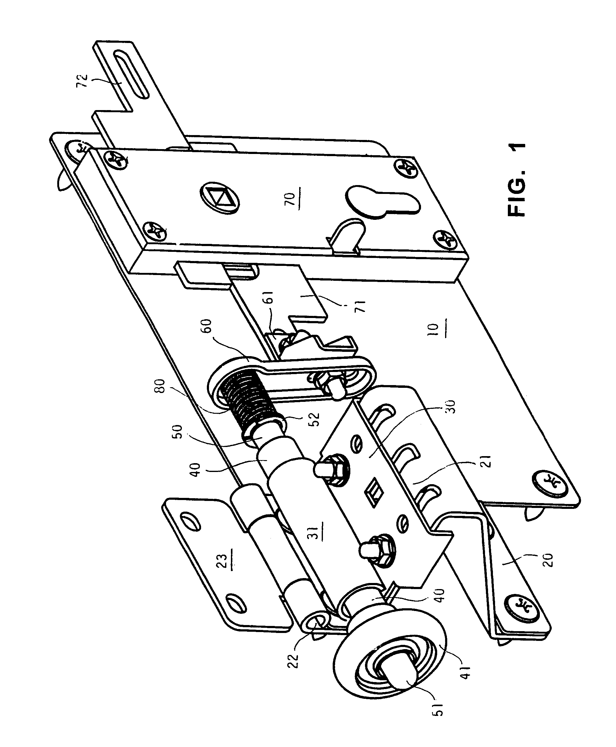
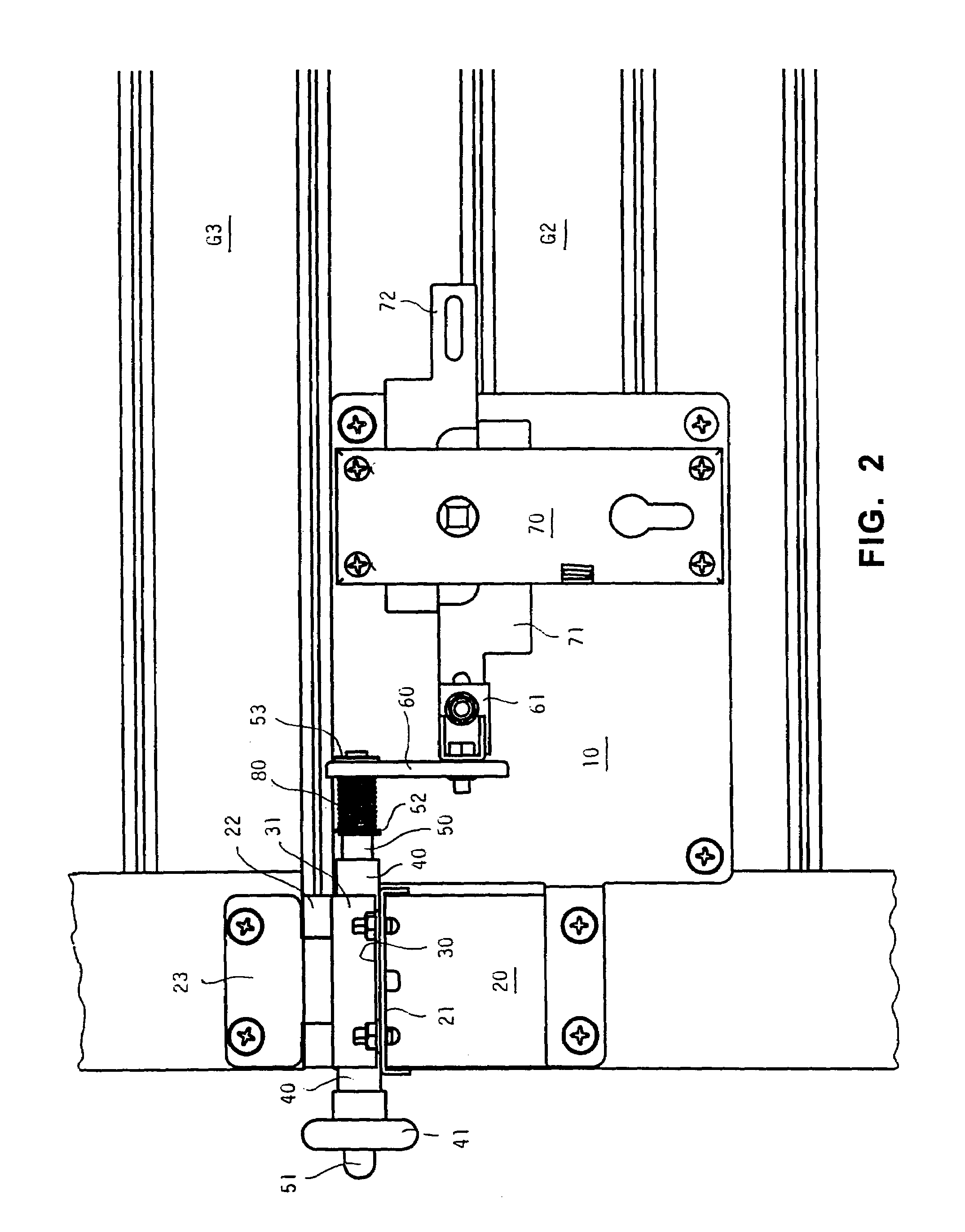
A latch for a section door wherein near the hinges located between the door elements there are provided, at each end of the elements, small rolling wheels which turn on horizontal pivots and slide within side guide bars having a vertical branch, an upper horizontal branch, and a curved connection branch located between the vertical and horizontal branches; the latch is located sideways and is intended for engaging, in its active position, in an opening provided in one of the side guide bars. The side latch is located coaxially with one of the small wheels intended to slide within the side guide bars of the section door. Preferably, the small wheel coaxial to the latch is mounted on a hollow pivot, and the latch is guided to slide within the bore of this hollow pivot.

Description

BACKGROUND OF THE INVENTION[0001]The subject of the present invention is a latch, mainly intended for the closure of a section door or the like. The invention also concerns some operating sets and an assembly, including said latch.[0002]The section doors are used mainly in the garages and the like, and they are formed by a number of sections in the shape of horizontally elongated elements, each connected to the adjacent ones by hinges, composing in their whole a rolling shutter which slides on side guide bars. In order to attain a quick running movement, near the hinges located between the shutter elements there are provided, at both ends of the shutter elements, small rolling wheels which turn on horizontal pivots or axles and roll within the side guide bars. Each side guide bar has a vertical branch which defines the operative position of the section door when closed, a upper horizontal branch which defines a disappearance position of the section door when open, and a curved conne...

Claims


Application Information

Patent Timeline
Patent Type & Authority Patents(United States)
IPC IPC(8): E05C1/12E05B47/00E05B53/00E05B65/00E05B65/08E05D15/16E05D15/24
CPCE05B65/0021E05D15/165E05B47/0012E05B53/003E05B65/0876Y10S292/36E05D15/24E05Y2900/106Y10S292/32E05B2047/0016Y10T292/0931Y10T292/0855Y10T292/0992Y10T292/1057Y10T292/083Y10T292/0841Y10T292/1017Y10T292/094Y10T292/096
Inventor FINARDI, IVO
Owner FINARDI IVO
Learn More