
Width detection method and width detection apparatus of record medium and record apparatus

a technology of width detection and record medium, which is applied in the direction of printing, other printing apparatus, etc., can solve the problems of difficulty in accurately finding the width of roll paper, and achieve the effect of accurate width detection, accurate width detection of record medium, and short tim

Inactive Publication Date: 2006-03-14
SEIKO EPSON CORP
View PDF1 Cites 14 Cited by
  • Summary
  • Abstract
  • Description
  • Claims
  • Application Information

AI Technical Summary

Benefits of technology

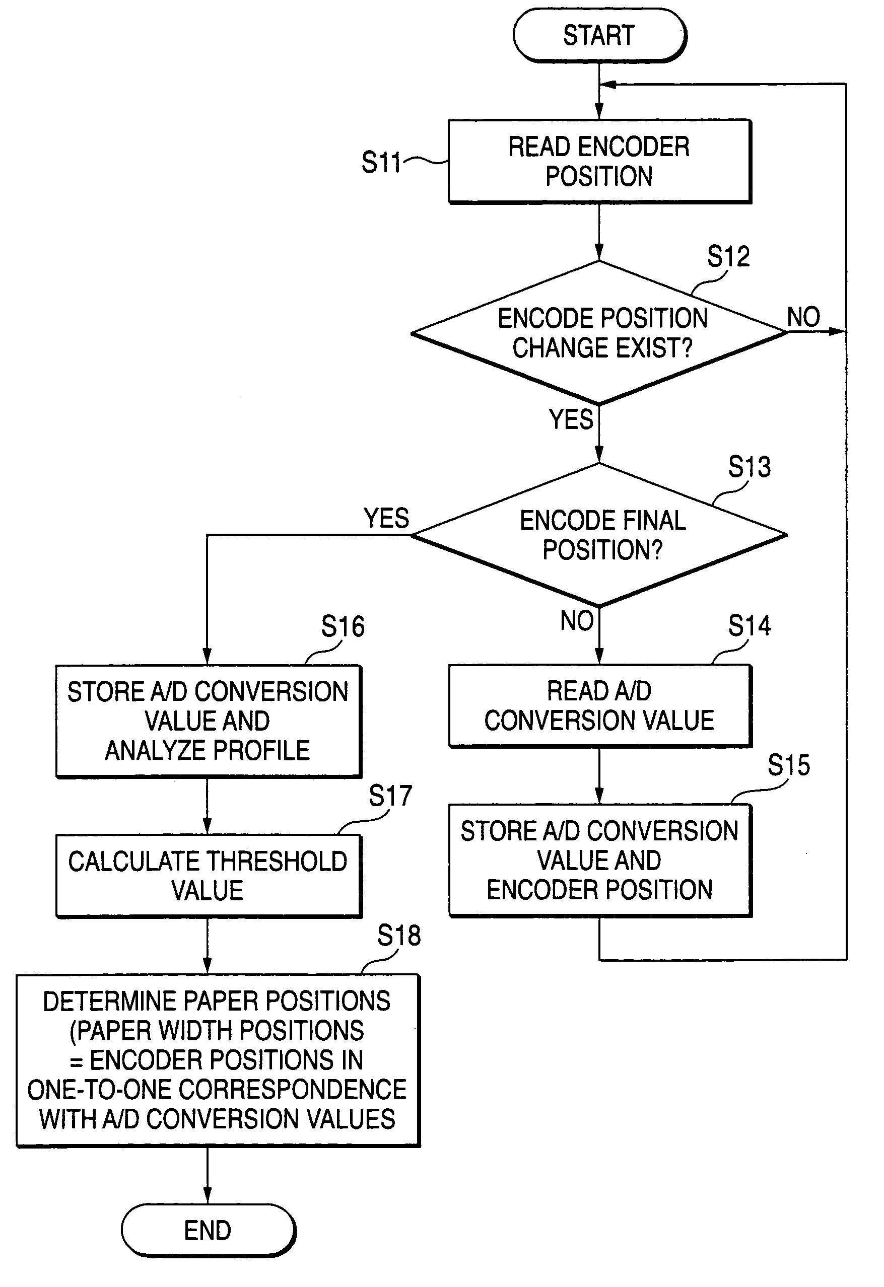
[0012]To the end, according to one aspect of the invention, there is provided a width detection method of a record medium for detecting the width of the record medium on which information is recorded by a recording head, the width detection method including the steps of storing the values of the detection signals of the record medium and the placement face thereof detected as the recording head moves from one end of the record medium to an opposite end; finding a predetermined threshold value based on a profile found from the values of the detection signals; and determining both ends of the record medium according to the threshold value and finding the width of the record medium. The threshold value may be found based on a profile of the values of all detection signals stored at the pulse interval input as the recording head moves from the one end of the record medium to the opposite end. The threshold value may be calculated based on the difference between the value of the detection signal of the record medium and the value of the detection signal of the placement face of the record medium. After the change rate of the value of the detection signal in the transition area between the end of the record medium and the placement face of the record medium is determined and what type the record medium is is determined, the threshold value may be calculated based on the difference between the value of the detection signal of the record medium and the value of the detection signal of the placement face of the record medium. Accordingly, the threshold value matching the used record medium can be set, so that an easy determination can be made as to whether or not change of the detection signal exceeding the threshold value occurs and change of the detection signal falling below the threshold value occurs, and the width of the record medium can be found accurately.
[0013]To the end, according to another aspect of the invention, there is provided a width detection apparatus of a record medium for detecting the width of the record medium on which information is recorded by a recording head, the width detection apparatus including medium detection means for sending the detection signals of the record medium and the placement face thereof detected as the recording head moves from one end of the record medium to an opposite end; transfer means for writing the detection signals from the medium detection means into storage means; computation processing means for finding a predetermined threshold value based on a profile found from the values of the detection signals stored in the storage means, determining both ends of the record medium according to the threshold value, and finding the width of the record medium. The width detection apparatus may further include head detection means for sending a pulse signal as the recording head moves, wherein the medium detection means may send the detection signals of the record medium and the placement face thereof at the pulse interval of the pulse signal from the head detection means and the computation processing means may find the predetermined threshold value based on a profile of the values of all detection signals stored in the storage means. The computation processing means may find the threshold value based on the difference between the value of the detection signal of the record medium and the value of the detection signal of the placement face of the record medium. The computation processing means may determine the change rate of the value of the detection signal in the transition area between the end of the record medium and the placement face of the record medium and determine what type the record medium is and then find the threshold value based on the difference between the value of the detection signal of the record medium and the value of the detection signal of the placement face of the record medium. Accordingly, the threshold value matching the used record medium can be set, so that an easy determination can be made as to whether or not change of the detection signal exceeding the threshold value occurs and change of the detection signal falling below the threshold value occurs, and the width of the record medium can be found accurately. In the related art, the CPU acquires the head position signal, determines position change of the recording head, sends a conversion start command of a detection signal, and acquires and stores detection signals. In the invention, however, the transfer means reads and writes the detection signals, so that each process can be completed in a short time and the record medium width detection time can be shortened drastically.
[0014]The transfer means may be a DMAC. The computation processing means may be a CPU. Accordingly, hardware processing rather than software processing can be performed as the processing, so that the read and write processing time of the detection signal can be shortened drastically.

Problems solved by technology

In roll paper not transported in an intimate contact state with a platen like thin paper, moderate output change is produced as the paper detection sensor 4 of the paper width detection apparatus in the related art described above crosses the boundary between the edge of roll paper and the platen surface, and it is difficult to accurately find the roll paper width by the method of determining whether or not change of exceeding the predetermined threshold value and change of falling below the predetermined threshold value occur as described above.

Method used


Image

  • Width detection method and width detection apparatus of record medium and record apparatus
  • Width detection method and width detection apparatus of record medium and record apparatus
  • Width detection method and width detection apparatus of record medium and record apparatus

Examples


Embodiment Construction

[0041]Referring now to the accompanying drawings, there are shown preferred embodiments of the invention.

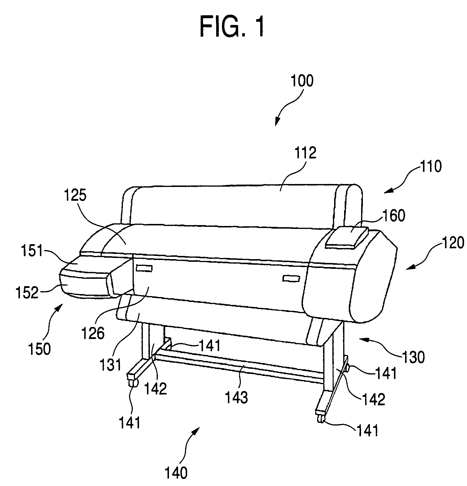
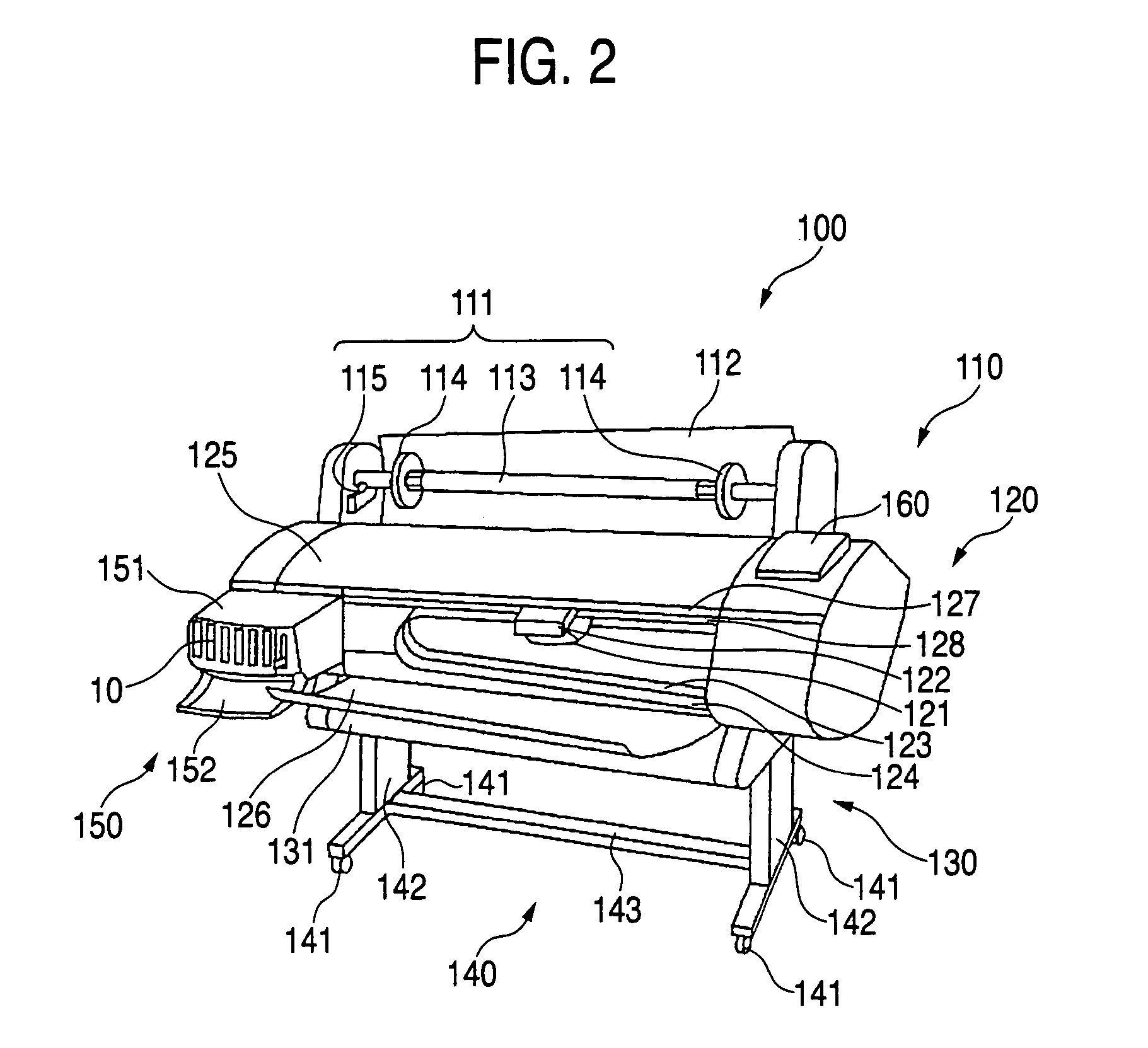
[0042]FIG. 1 is a perspective view to show a structure example of an ink jet printer, one of record apparatus according to an embodiment of the invention. FIG. 2 is a perspective view to show an internal structure example of the main part of the ink jet printer. The ink jet printer 100 shown in FIGS. 1 and 2 is a large printer that can record up to record paper of comparatively large sizes such as A1 size of the JIS standard and B1 size of the JIS standard, for example, and has a paper feed section 110, a record section 120, a paper ejection section 130, and a leg section 140 disposed in this order from top to bottom. The record section 120 and the paper ejection section 130 are integral as the main unit and can be separated from the paper feed section 110 and the leg section 140.

[0043]The paper feed section 110 is placed so as to project to the upper rear of the main unit 120, 1...


PUM


Abstract

The values of the detection signals of a record medium and the placement face thereof detected as a recording head moves from one end of the record medium to an opposite end are stored. A predetermined threshold value is found based on a profile found from the stored values of the detection signals. Both ends of the record medium are determined according to the threshold value and the width of the record medium is found. Accordingly, the threshold value matching the used record medium can be set, so that an easy determination can be made as to whether or not change of the detection signal exceeding the threshold value occurs and change of the detection signal falling below the threshold value occurs, and the width of the record medium can be found accurately.

Description

BACKGROUND OF THE INVENTION[0001]This invention relates to a width detection method and a width detection apparatus for detecting the width of a record medium on which information is recorded by a recording head, and a record apparatus including the width detection apparatus.[0002]Generally, a large printer, one of record apparatus in related arts, includes a paper feed section for supplying record roll paper, for example, as a record medium, a record section for recording information on supplied roll paper, and a paper ejection section for ejecting the roll paper with information recorded, disposed in this order from top to bottom. To use such a large printer, for example, an ink jet printer, the user stores roll paper in the paper feed section and draws out the leading edge of the roll paper. The user passes the leading edge of the roll paper through the top of a flat paper feed guide serving as a paper transport face and sandwiches the leading edge between a paper feed roller and...

Claims


Application Information

Patent Timeline
IPC IPC(8): B41J2/01B41J11/00
CPCB41J11/0095B41J11/0025
Inventor NAKANO, SHUICHI
Owner SEIKO EPSON CORP
Learn More