Polarization converter, an illumination optical device having the polarization converter and projector

Inactive Publication Date: 2006-03-14
SEIKO EPSON CORP
View PDF8 Cites 21 Cited by
  • Summary
  • Abstract
  • Description
  • Claims
  • Application Information

AI Technical Summary

Benefits of technology

[0035]According to the above projector of the present invention, since the above illumination optical device is provided, an object of the present invention can be achieved as described above and the other advantages can be attained in the same manner. Further, by using

Problems solved by technology

Such polarization converter has an ineffective area, where the light beam is directly incident on the reflecting film without passing through the polarization separating film to be irradiated as ineffective polarization light.
However, according to the above polarization converter, the retardation plates attached to opposing sides of

Method used


Image

  • Polarization converter, an illumination optical device having the polarization converter and projector
  • Polarization converter, an illumination optical device having the polarization converter and projector
  • Polarization converter, an illumination optical device having the polarization converter and projector

Examples


first embodiment

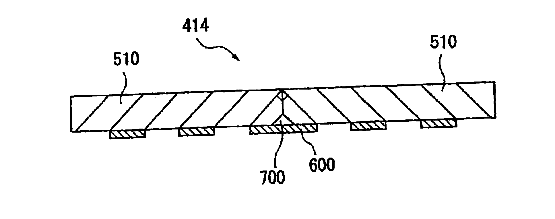
[0148]According to the above first embodiment, following advantages can be obtained.[0149](1) Since the polarizing conversion element array 500 of the polarization converter 414 has the pair of polarizing conversion elements 510 and the pair of polarizing conversion elements 510 are in close contact so that mutual polarization separating films 511 and the reflecting films 512 are opposed, the random polarization light passing through the gap between the two polarizing conversion elements 510 (illumination optical axis) can be converted into effective polarization light (S polarization light), thus enhancing luminance of the projector 1.[0150](2) Since the retardation plate 600 located on the illumination optical axis is adhered stretching over the two polarizing conversion elements 510, there is no interference of the mutual retardation plate 600 caused when the two polarizing conversion elements 510 are brought into close contact, so that it is not necessary to strictly determine t...

second embodiment

[Second Embodiment]

[0157]Next, second embodiment of the present invention will be described below with reference to attached drawings.

[0158]In the following description, the same reference numeral will be attached to the same structure and the same component to omit or simplify the detailed description thereof.

[0159]In the first embodiment, the polarizing conversion element 510 is formed in approximately rectangular parallelepiped so that the ends of the two polarizing conversion elements 510 directly contact to be flush with each other when the two polarizing conversion elements 510 are brought into close contact.

[0160]On the other hand, in the second embodiment, an end of the light-irradiation side of the rectangular parallelepiped polarizing conversion element 510 is chipped, so that a notch 700 is formed on the contact portion between the retardation plate 600 and the two polarizing conversion elements 510 when the two polarizing conversion elements 510 are closely contacted and...


PUM


Abstract

A polarizing conversion element array (500) of a polarization converter (414) has two polarizing conversion elements (510) provided with a polarization separating film (511) for separating a light beam into two linearly polarization beams and a reflecting film (512) that reflects one of the linearly polarization beams separated by the polarization separating film (511) in an alternate manner, the two polarizing conversion elements (510) being arranged so that the respective polarization separating films (511) and the reflecting films (512) are opposed, the polarization converter (414) being constructed by adhering a retardation plate (600) on a light-irradiation side of the polarizing conversion element array (500) stretching over the two polarizing conversion elements (510).

Description

BACKGROUND OF THE INVENTION[0001]1. Field of the Invention[0002]The present invention relates to a polarization converter for converting a light beam from a light source into a single linearly polarization beam, an illumination optical device having the polarization converter and a projector.[0003]2. Description of Related Art[0004]Conventionally, a projector has been used for presentation at a conference, academic society and exhibition. Such projector accommodates a plurality of optical components in a casing, where a light bean irradiated by a light source is enlarged and projected after being modulated by the light components to form a projection image.[0005]A polarization converter for converting the light beam from the light source into a single linearly polarization beam is used for enhancing utilization efficiency of the light beam to obtain a bright projection image.[0006]The polarization converter has a polarizing conversion element having a polarization separating film in...

Claims


Application Information

Patent Timeline
IPC IPC(8): G03B21/14G03B21/28G02B5/30G02B27/28G02F1/13G02F1/1335G02F1/13357G03B21/00H04N5/74
CPCG02B27/286
Inventor OGAWA, YASUNORIKAWAI, FUMIE
Owner SEIKO EPSON CORP
Why Eureka
Try Eureka