Portable hoisting device

Inactive Publication Date: 2006-03-14
DYER ROBERT ANTHONY
View PDF13 Cites 15 Cited by
  • Summary
  • Abstract
  • Description
  • Claims
  • Application Information

AI Technical Summary

Problems solved by technology

This bearing assembly is reinforced because the sidewalls of a pickup truck are not, by t

Method used


Image

  • Portable hoisting device
  • Portable hoisting device
  • Portable hoisting device

Examples


Embodiment Construction

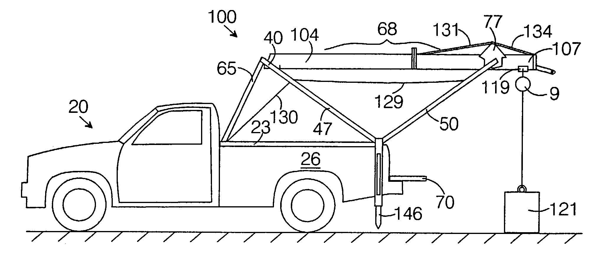
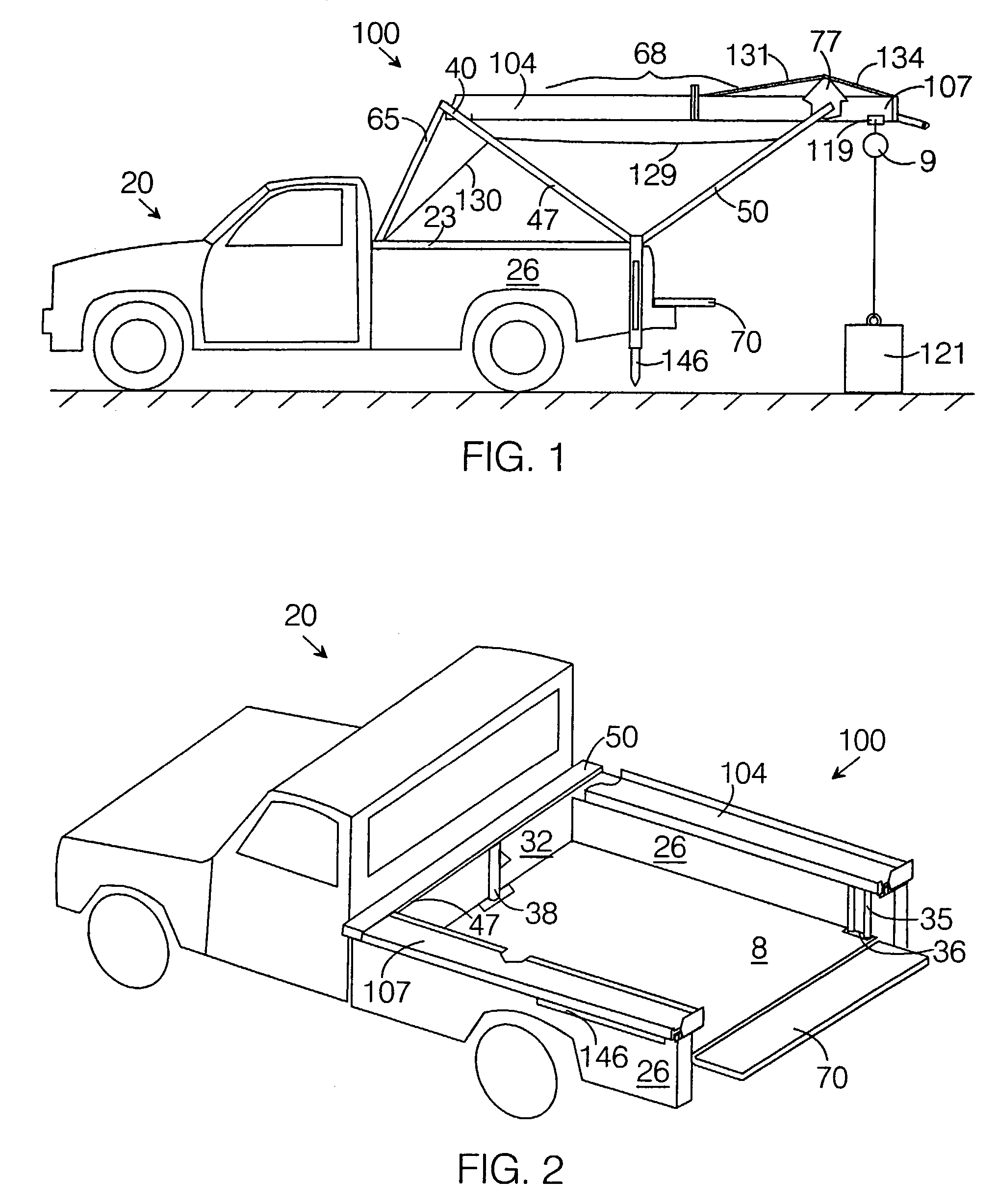
[0054]FIG. 1 and FIG. 2 depict the deployed and stowed configurations, respectively, of the Preferred Embodiment hoist 100 of the invention, mounted on a conventional pick-up truck 20. The truck 20 on which the hoist 100 is mounted has a bed 8 bordered by sidewalls 26, a front wall 32, and a tailgate 70. The hoist 100 includes a mounting frame 23 and a support frame 40. The support frame 40 is made up principally of a front yoke 47, a rear yoke 50 and a front yoke brace 65.

[0055]FIG. 1 shows the hoist 100 engaged in starting to lift a load 121, which will be conveyed using a beam trolley 119 along a trolley rail 68. The load 121 is being lifted by the chain hoist 9, which is being supported by the beam trolley 119, which bears on the lower flange of the trolley rail 68. Downriggers 146 are shown attached to that part of the mounting frame 23 that is located near the rear of the sidewalls 26. The downriggers 146 are seen to not quite reach the ground. As more of the load 121 is borne...


PUM


Abstract

A collapsible, portable hoist that can be assembled and operated by a single individual, for lifting and conveying heavy objects onto and off of trucks, especially pickup trucks. When not in use, the hoist collapses down to a flat storage configuration that rests on, and is secured to, the truck's cargo walls without any portion extending beyond the truck. In order to deploy the hoist, one rotates its support frame up from the stowed position and then suspends from it the rail along which a trolley or other implement used to convey the object will travel. When the hoist is fully deployed, the trolley rail is mounted high above the bed, permitting tall objects to be manipulated. The hoist is constructed so as to be readily removable from the truck.

Description

BACKGROUND OF THE INVENTION[0001]1. Field of the Invention[0002]This invention relates to hoisting devices. More particularly, this invention relates to a collapsible and portable hoisting device for lifting heavy loads. More particularly still, this invention relates to such a hoisting device configured to be stowed on a small truck, such as a pickup truck, in such a manner that it is available for ready deployment and use in moving a heavy object either onto or off of the truck.[0003]2. Description of Prior Art[0004]Hoisting devices are used to lift and convey objects weighing several hundred to several thousand pounds without the need to use power equipment such as forklifts or mobile cranes. Numerous such devices are used in industrial settings, where they are often used to load and unload trucks. Industrial-sized hoists for such purposes are typically very large and usually permanently installed at hoisting stations dedicated to the requirements of a particular type of truck. T...

Claims


Application Information

Patent Timeline
IPC IPC(8): F16B43/02B60P1/54
CPCB60P1/54B60P1/549B60P1/5428
Inventor DYER, ROBERT ANTHONY
Owner DYER ROBERT ANTHONY
Why Eureka
Try Eureka