Supercharge Your Innovation With Domain-Expert AI Agents!

Forming a transparent window in a polishing pad for a chemical mechanical polishing apparatus

a technology of polishing apparatus and polishing pad, which is applied in the direction of grinding device, tapping machine, instruments, etc., can solve the problems of poor yield and device performance, high topography of in-process wafer, and uneven topography of the wafer

Inactive Publication Date: 2006-03-14
APPLIED MATERIALS INC
View PDF66 Cites 22 Cited by
  • Summary
  • Abstract
  • Description
  • Claims
  • Application Information

AI Technical Summary

Problems solved by technology

However, the prior formations often leave the top surface topography of an in-process wafer highly irregular, with bumps, areas of unequal elevation, troughs, trenches, and / or other surface irregularities.
These irregularities cause problems when forming the next layer.
In addition, if the irregularities are not leveled at each major processing step, the surface topography of the wafer can become even more irregular, causing further problems as the layers stack up during further processing.
Depending on the die type and the size of the geometries involved, the surface irregularities can lead to poor yield and device performance.
However, some pads have only a covering layer and no backing layer.
A particular problem encountered during a CMP process is in the determination that a part has been planarized to a desired flatness or relative thickness.
Early on, it was not possible to monitor the characteristics of the wafer during the CMP process.
This was a time consuming and labor-intensive procedure.
Alternately, the examination might have revealed that an excess amount of material had been removed, rendering the part unusable.

Method used


Image

  • Forming a transparent window in a polishing pad for a chemical mechanical polishing apparatus
  • Forming a transparent window in a polishing pad for a chemical mechanical polishing apparatus
  • Forming a transparent window in a polishing pad for a chemical mechanical polishing apparatus

Examples


Embodiment Construction

)

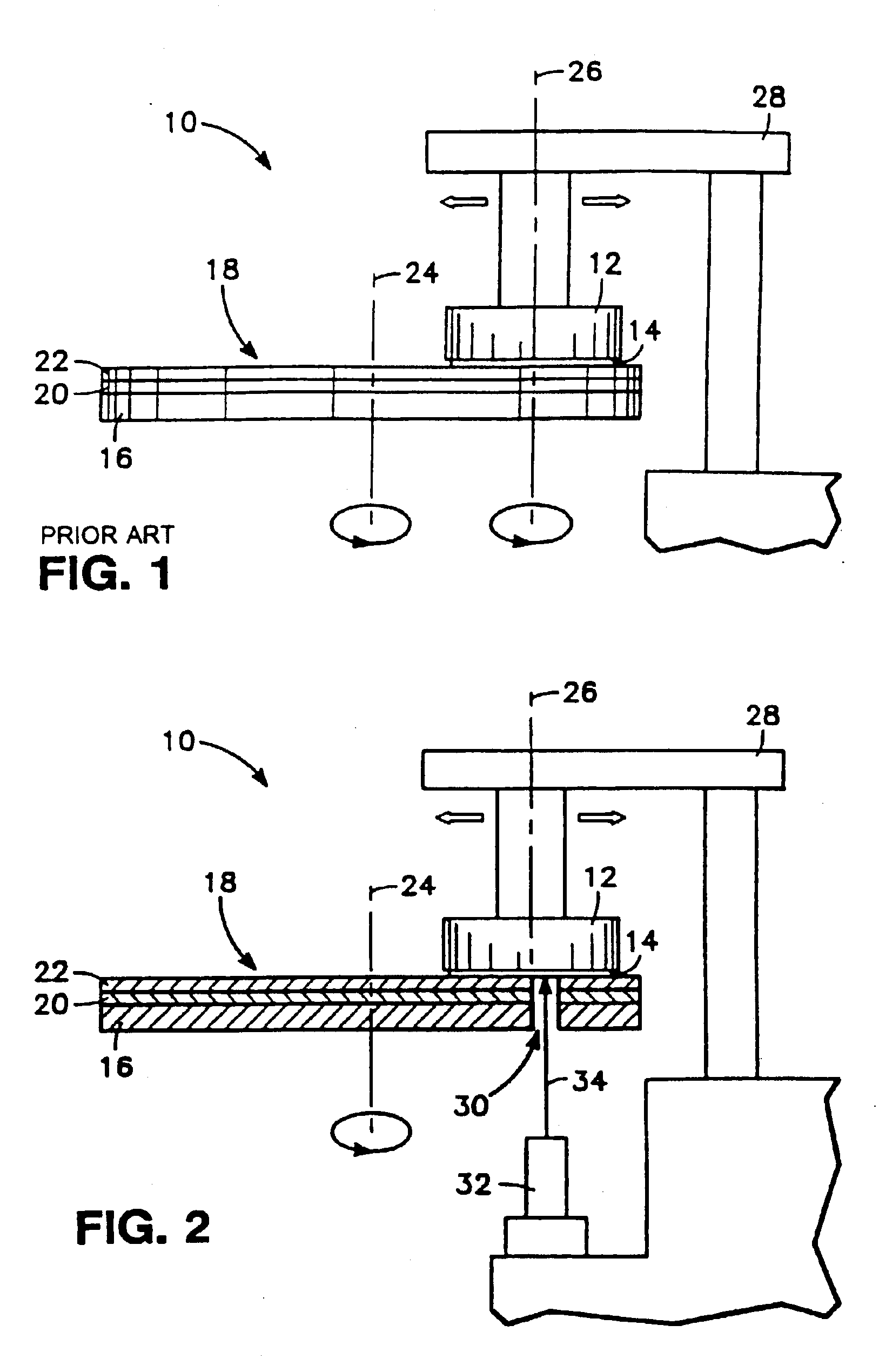
[0040]FIG. 2 depicts a portion of a CMP apparatus modified in accordance with one embodiment of the present invention. A hole 30 is formed in the platen 16 and the overlying platen pad 18. This hole 30 is positioned such that it has a view of the wafer 14 held by a polishing head 12 during a portion of the platen's rotation, regardless of the translational position of the head 12. A laser interferometer 32 is fixed below the platen 16 in a position enabling a laser beam 34 projected by the laser interferometer 32 to pass through the hole 30 in the platen 16 and strike the surface of the overlying wafer 14 during a time when the hole 30 is adjacent the wafer 14.

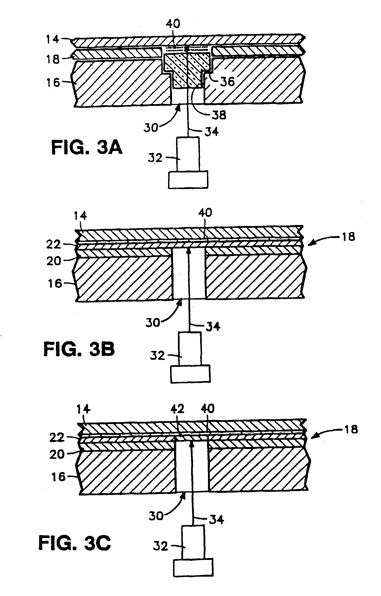
[0041]A detailed view of the platen hole 30 and wafer 14 (at a time when it overlies the platen hole 30) are shown in FIGS. 3A-C. As can be seen in FIG. 3A, the platen hole 30 has a stepped diameter, thus forming a shoulder 36. The shoulder 36 is used to contain and hold a quartz insert 38 which functions as a window for the ...


PUM


Abstract

The polishing pad for a chemical mechanical polishing apparatus, and a method of making the same. The polishing pad has a covering layer with a polishing surface and a backing layer which is adjacent to the platen. A first opening in the covering layer with a first cross-sectional area and a second opening in the backing layer with a second, different cross-sectional area form an aperture through the polishing pad. A substantially transparent polyurethane plug is positioned in the aperture, and an adhesive material fixes the plug in the aperture.

Description

CROSS REFERENCE TO RELATED APPLICATIONS[0001]This application is a continuation of pending U.S. patent application Ser. No. 09 / 863,118, filed May 22, 2001, which is a continuation of U.S. patent application Ser. No. 09 / 519,156, filed Mar. 6, 2000, now U.S. Pat. No. 6,280,290, which is a continuation of U.S. patent application Ser. No. 09 / 258,504, filed Feb. 26, 1999, issued as U.S. Pat. No. 6,045,439, which is a continuation of U.S. patent application Ser. No. 08 / 689,930, filed Aug. 16, 1996, issued as U.S. Pat. No. 5,893,796, which is continuation-in-part of U.S. patent application Ser. No. 08 / 605,769, filed Feb. 22, 1996, issued as U.S. Pat. No. 5,964,643, which is a continuation-in-part of U.S. patent application Ser. No. 08 / 413,982, filed Mar. 28, 1995, abandoned.BACKGROUND[0002]This invention relates generally to semiconductor manufacture, and more particularly to a method for forming a transparent window in a polishing pad for use in chemical mechanical polishing (CMP).[0003]I...

Claims


Application Information

Patent Timeline
Patent Type & Authority Patents(United States)
IPC IPC(8): B24B49/00B24B37/04B24B47/12B24B49/02B24B49/04B24B49/12B24B51/00B24D7/12B24D13/14G01B11/06H01L21/304
CPCB24B37/013B24B37/205B24B47/12B24B49/04G01B11/0683B24B51/00B24D18/00G01B11/06B24B49/12B24B37/04
Inventor BIRANG, MANOOCHERGLEASON, ALLANGUTHRIE, WILLIAM L.
Owner APPLIED MATERIALS INC
Features
  • R&D
  • Intellectual Property
  • Life Sciences
  • Materials
  • Tech Scout
  • Unparalleled Data Quality
  • Higher Quality Content
  • 60% Fewer Hallucinations
Learn More