
Insert for a bat having an improved seam orientation

a seam orientation and inserting technology, applied in the field of inserting for ball bats, can solve the problems of undesirable local plastic deformation, too stiff to achieve optimum slugging performance, adverse effect of bat performance, etc., and achieve the effect of reducing bat performance, superior durability characteristics, and reducing the number of inserts

Inactive Publication Date: 2006-03-14
WILSON SPORTING GOODS
View PDF21 Cites 35 Cited by
  • Summary
  • Abstract
  • Description
  • Claims
  • Application Information

AI Technical Summary

Benefits of technology

[0012]The present invention provides an improved baseball or softball bat with superior durability characteristics and little or no reduction in bat performance. The invention does so by providing a relatively thin, light (but strong) composite material, with directional strength characteristics to resist dent-causing forces, in bonded relationship to a metal carrier. For example, the present invention includes a single- or multi-wall tubular bat having at least one composite layer, with its greatest strength in a substantially circumferential direction, bonded directly to a tubular member which deflects upon ball impact.
[0013]According to a principal aspect of the invention, a bat includes a tubular frame and a tubular insert reinforced with at least one composite layer. The composite layer has its greatest strength in a substantially circumferential direction and is bonded to at least a portion of the outer surface of the insert. The composite layer provides several advantages, including improved durability with little or no reduction in performance. Because the composite layer adds strength and stiffness to the insert in the circumferential direction, it helps prevent local plastic deformation caused by circumferential stresses while allowing the frame and insert to deflect sufficiently in the axial direction to transfer substantial energy back to the ball as it leaves the surface of the bat. In another embodiment, the composite layer(s) is bonded to at least a portion of the inner surface of the insert.

Problems solved by technology

For example, an attempt to increase the durability of the bat often produces an adverse effect on the bat's performance.
Consequently, a bat having a relatively thin tubular wall is capable of large elastic deflection, but may be vulnerable to undesirable local plastic deformation (or “denting”).
On the other hand, a relatively thick tubular wall is more durable but may be too stiff to achieve optimum slugging performance.
Thus, enhancing one design aspect of a bat often compromises another.
In addition, an increase in the overall size of the bat undesirably adds weight, often causing reduced bat speed and less slugging distance.
This design gives the bat a relatively stiff, rigid tubular frame which appears to be capable of limited elastic deformation, a less than ideal trait if the goal is to optimize slugging performance.
While composite materials offer the advantage of a high strength to weight ratio, such materials also present design challenges.
Composite inserts and bat frames are prone to wear and tear due to the inter-laminar shear which can occur between bonded layers of composite material.
The deflection caused when a ball impacts the bat produces shearing stresses between the composite layers, sometimes causing the bond between adjacent layers to fracture or separate (especially over time).
Further, a bat including at least one composite layer having a longitudinally extending seam, can have inconsistent or varied performance characteristics depending upon the orientation of the bat, and in particular the location of the seam of the composite layer, in relation to the location of impact with the ball.
Thus, despite the advantages offered by composite materials, there are a number of drawbacks associated with using such materials including the potential for reduced elastic deflection, a tendency of the composite layers to separate over time due to inter-laminar shear, the susceptibility of the composite insert to fail along the longitudinal seam of the insert, and inconsistent slugging performance resulting from a longitudinal seam of a composite layer of a bat.

Method used


Image

  • Insert for a bat having an improved seam orientation
  • Insert for a bat having an improved seam orientation
  • Insert for a bat having an improved seam orientation

Examples


Embodiment Construction

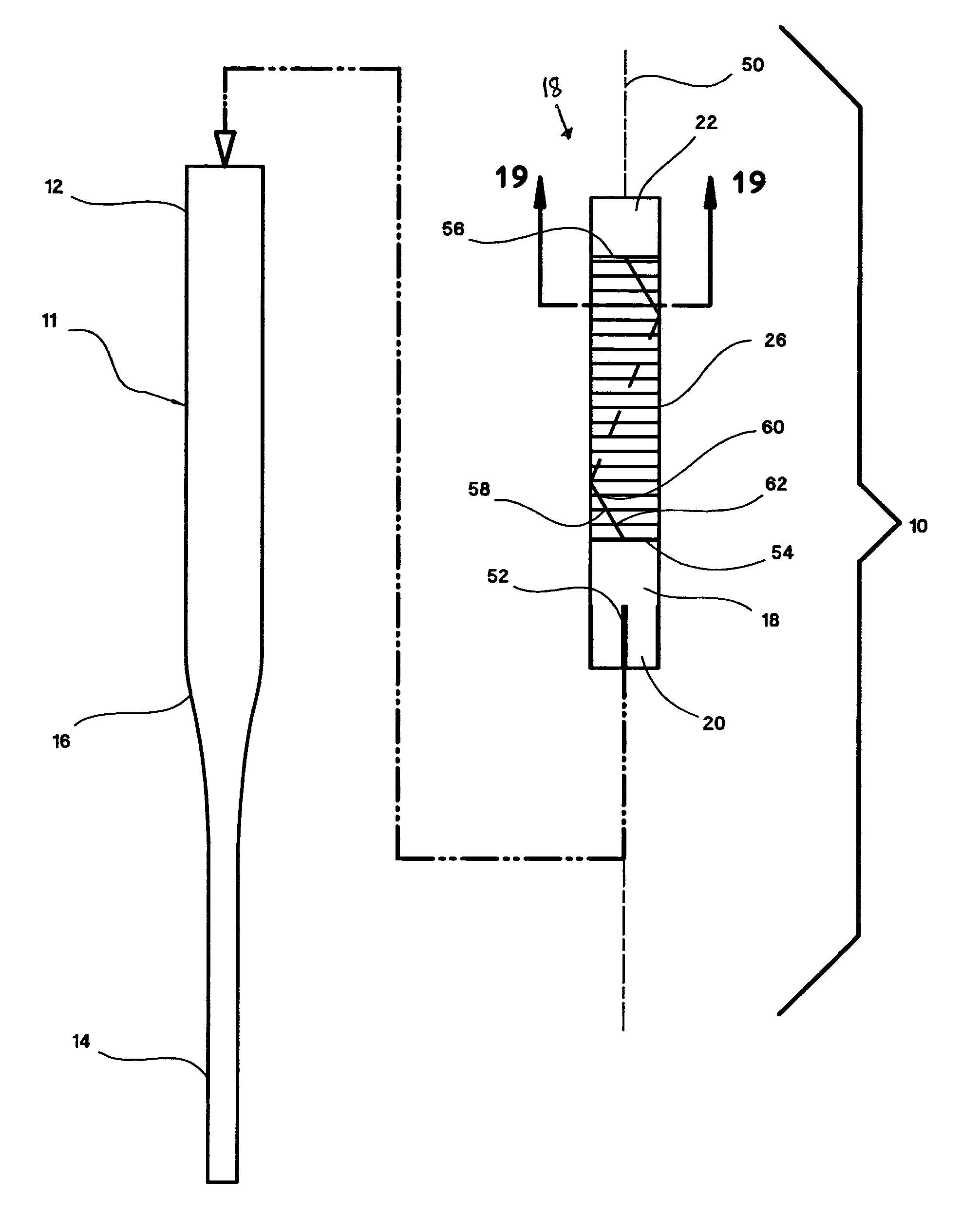
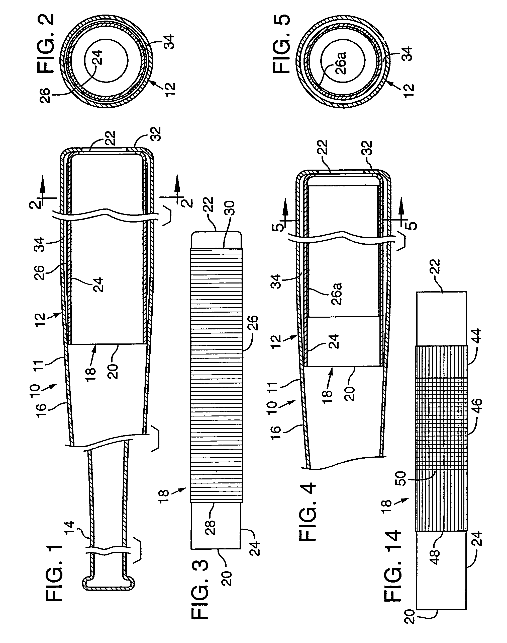
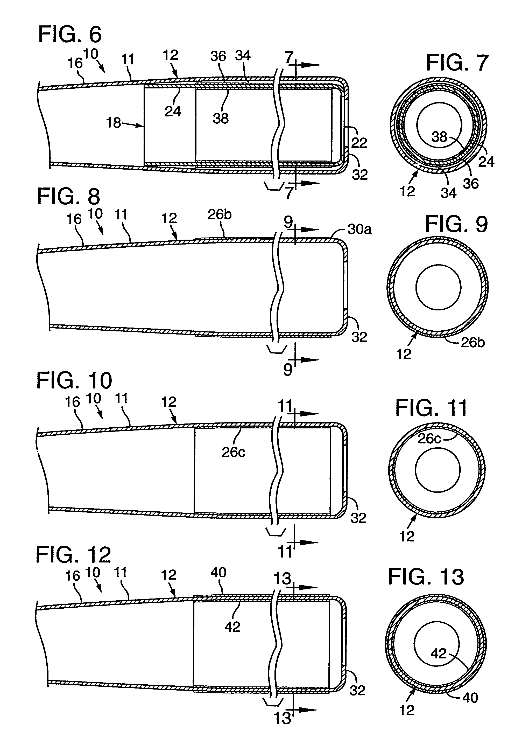
[0050]Referring to FIG. 1, a tubular bat 10, according to one embodiment of the present invention, has a tubular frame 11 with a relatively large constant-diameter impact portion 12, a relatively small diameter handle portion 14, and an intermediate tapered portion 16 that extends between the handle and impact portions. The impact portion 12 is “tubular” or “substantially tubular,” terms intended to encompass softball style bats having a substantially cylindrical impact portion (or “barrel”) as well as baseball style bats having a substantially conical (or “frustum-like”) barrel.

[0051]The tubular frame 11 engages a tubular insert 18 within the impact portion 12. The bat 10 provides two essentially parallel walls in the “hitting zone” or barrel region. The insert 18 is restrained within the tubular frame 11 either by retaining the ends of the insert in place or at least trapping the insert within the barrel to permit some axial movement. As shown in FIG. 1, for example, a first end 2...


PUM


Abstract

A bat includes a substantially tubular frame, a substantially tubular body and at least one sheet. The frame extends along a longitudinal axis. The frame has a handle portion and a primary hitting portion. The body is coaxially aligned with the hitting portion of the frame. The sheet has a proximal edge, a distal edge, and first and second side edges. The sheet is coupled to at least a portion of one of the hitting portion of the frame and the body such that the first and second edges each extend from the proximal edge to the distal edge along a path that is substantially non-parallel with the longitudinal axis.

Description

RELATED U.S. APPLICATION DATA[0001]The present application is a continuation of U.S. patent application Ser. No. 10 / 033,805, entitled “Insert For A Bat Having An Improved Seam Orientation,” filed on Dec. 28, 2001 now U.S. Pat. No. 6,733,404 by Fritzke et al., which is a continuation-in-part of U.S. patent application Ser. No. 09 / 396,700, entitled “Ball Bat,” filed on Sept. 15, 1999 by Fritzke et al., now U.S. Pat. No. 6,497,631.FIELD OF THE INVENTION[0002]The present invention relates generally to baseball and softball bats. In particular, the present invention relates to an insert for a ball bat, which is formed at least in part from at least one layer of composite material having an improved seam orientation.BACKGROUND OF THE INVENTION[0003]Recent years have seen an emergence of new and improved tubular metallic softball and baseball bats. The most common tubular bat is the aluminum single-wall tubular bat. Such bats have the advantage of a generally good impact response, meaning ...

Claims


Application Information

Patent Timeline
Patent Type & Authority Patents(United States)
IPC IPC(8): A63B59/06
CPCA63B59/06A63B59/50A63B59/51A63B2102/18
Inventor FRITZKE, MARK A.EGGIMAN, MICHAEL D.GARNETT, WILLIAM JEROME
Owner WILSON SPORTING GOODS
Learn More