Puncture wound bandage

a puncture wound and bandage technology, applied in the field of puncture wound bandage, can solve the problems of untidy disposal of gauze upon removal, discomfort and/or inconvenience of patients, and the most common dressing for puncture wound due to the use of blood withdrawal cannulas is still primitive, so as to reduce the risk of contamination, save costs, and save costs.

Inactive Publication Date: 2006-03-14
TOMAIOULO THEODORE B
View PDF34 Cites 47 Cited by
  • Summary
  • Abstract
  • Description
  • Claims
  • Application Information

AI Technical Summary

Benefits of technology

[0005]There is, accordingly, a need in the art for novel methods, systems and apparatus for more reliably, efficiently and / or economically dressing puncture wounds. Such methods and apparatus should be well-suited to controlled medical environments such as clinics, hospitals, blood banks, blood drives, medical offices, etc. in which blood is intentionally drawn from patients. Further, such methods and apparatus should also be capable of dressing biopsy wounds. However, such methods and apparatus would also be useful to dress accidental puncture wounds. Such methods and apparatus should solve the above stated deficiencies without introducing additional expense and complexity to the blood-removal process. Accordingly, such methods and apparatus should reduce the risk of contamination, be easy to use and require little, if any, packaging.
[0006]The present invention satisfies the above-stated needs and overcomes the above-stated and other deficiencies of the related art by providing methods, systems and apparatus for safely, efficiently and economically dressing puncture wounds.
[0007]One aspect of the present invention is directed to a sealed bandage in which a bandage with an absorbent pad affixed to an adhesive strip is packaged by affixation to a complementary carrier with a blister, to accommodate the pad, and with at least one end region of the bandage as defined by a means for separating (for example, a snap-line) portions of the carrier. The carrier is formed of a material that is substantially more rigid than the adhesive strip and is weakened at the snap-line(s) such that a user may break the carrier along the snap line and peel the carrier from the adhesive strip except for the end region(s) thereof. A snap-line may be shaped in one of a number of configurations, but is preferably shaped to facilitate grasp of the carrier upon breakage along the snap-line.

Problems solved by technology

Although there is a wide range of bandages in use today, the most common dressing for a puncture wound due to the use of a blood withdrawal cannula is still primitive.
Naturally, requiring a patient to maintain this position for an extended period of time creates a number of problems.
These may include (1) wound infection resulting from gauze contamination before application to the patient; (2) wound infection resulting from a patient's unwillingness and / or inability to maintain this position for a sufficient time; (3) discomfort and / or inconvenience to the patient; and / or (4) untidy disposal of the gauze upon removal, as intended or accidentally.
While this helps ensure that the gauze remains in place longer, it also creates several problems of it's own.
These problems include: (1) the risk that the tape will be inadvertently and / or prematurely pulled loose from the patient; (2) the additional time and expense that a phlebotomist must devote to tape the gauze in place; and / or (3) the risk of wound infection resulting from gauze contamination before application to the patient.

Method used


Image

  • Puncture wound bandage
  • Puncture wound bandage
  • Puncture wound bandage

Examples


Embodiment Construction

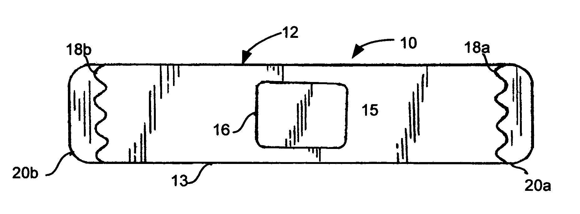
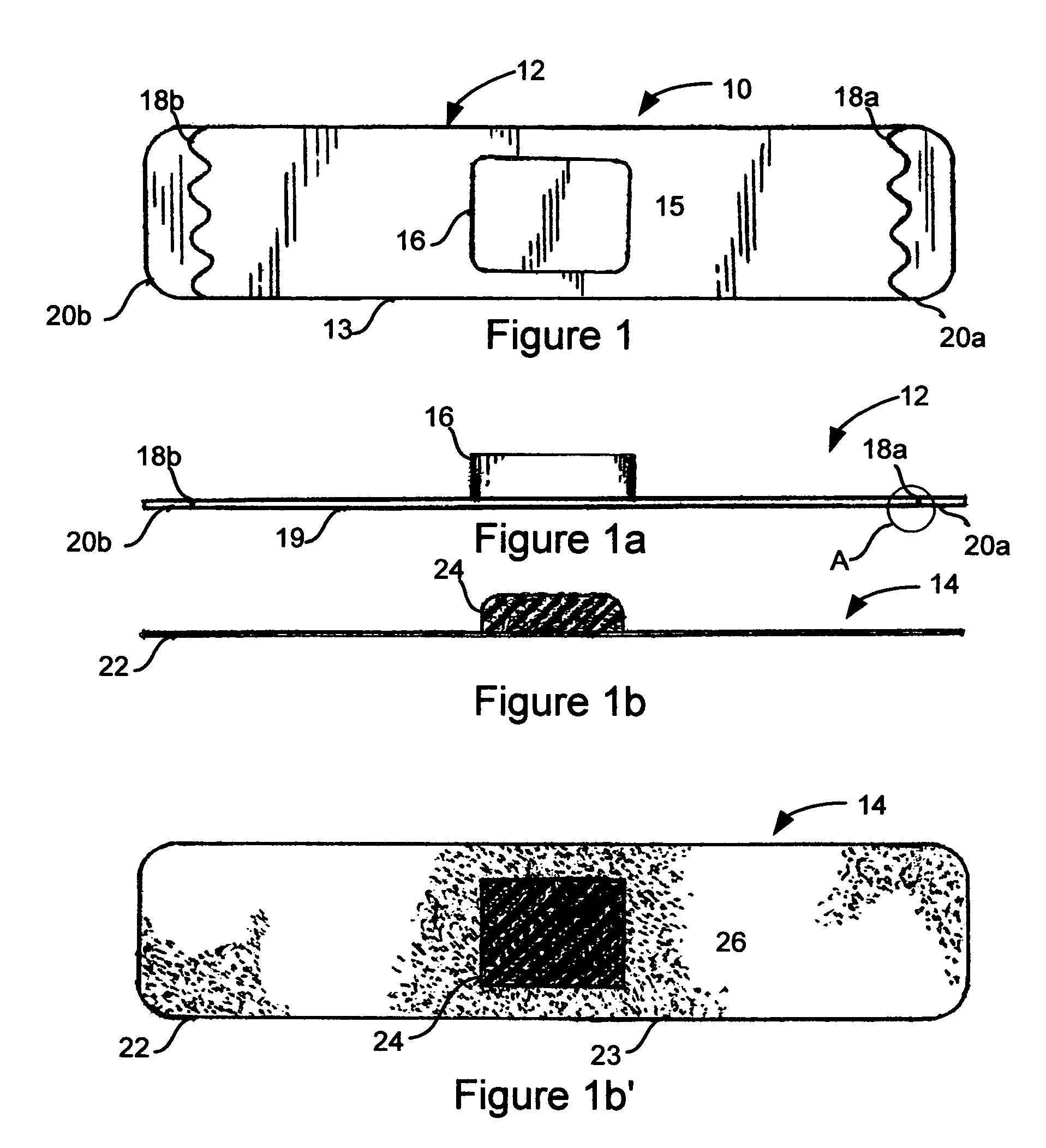
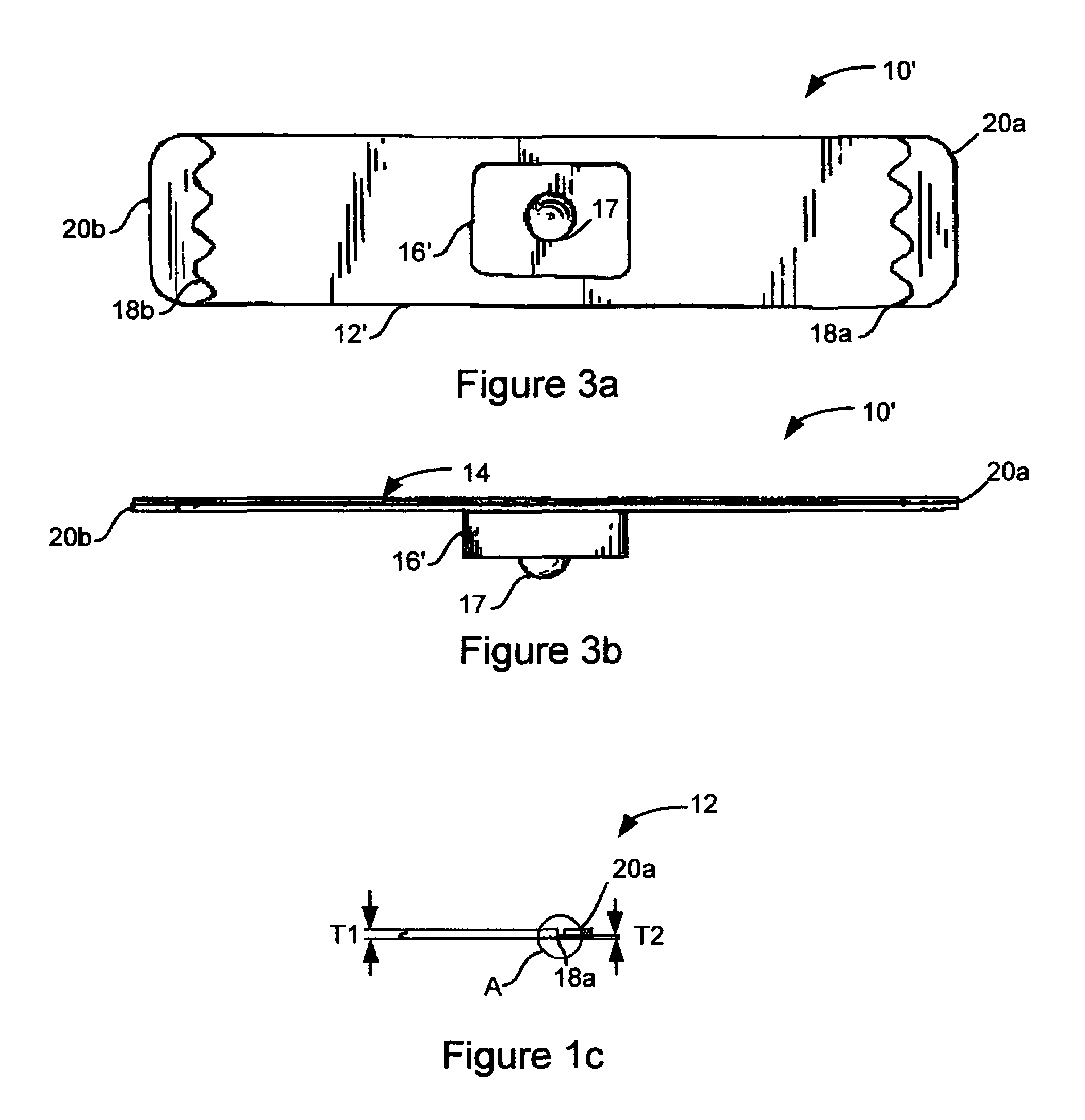
[0025]A first preferred embodiment of the invention will now be described with joint reference to accompanying FIGS. 1, 1a, 1b, 1b′ and 1c. As shown therein, FIG. 1 is a top plan view of a sealed bandage in accordance with one preferred embodiment of the present invention. A side elevation view of the bandage carrier shown in FIG. 1 is illustrated in FIG. 1a. FIG. 1b is a side elevation view of the bandage of FIG. 1. FIG. 1b′ is a top plan view of the bandage of FIG. 1b and FIG. 1c is a partial side elevation view of the carrier of FIG. 1a illustrating detail A.

[0026]As shown in these Figures, a sealed bandage 10 comprises a carrier 12 and a bandage 14 having an adhesive strip 22 with an adhesive surface 26 that defines an outer perimeter 23. Sealed bandage 10 is preferably about six inches long and between 1 inch and 1¼ inches wide for use as a dressing for a standard needle puncture wound. As discussed herein, the inventive bandage is preferably sized, shaped and constructed so th...


PUM


Abstract

Advancements in bandages for treating puncture wounds shown and described herein include sealed bandage with flexible adhesive strips disposed on more rigid carriers with at least one separation line. Bending the sealed bandages separates the carrier along the path of the separation line(s) to thereby pull the strip away from the carrier in the vicinity of the separation line such that at least a portion of the carrier may be pulled from the strip and the bandage applied to a patient. This abstract is provided for the sole purpose of complying with the rules requiring an abstract to allow a searcher or other reader to quickly ascertain the subject matter of the technical disclosure contained herein. This abstract is submitted with the express understanding that it will not be used to interpret or to limit the scope or the meaning of the claims.

Description

BACKGROUND OF THE INVENTION[0001]1. Field of the Invention[0002]The present invention is directed to systems, methods, apparatus and / or devices for dressing human and / or animal wounds. More particularly, the invention relates to the field of dressing puncture wounds with a bandage. Accordingly, the general objects of the invention are to provide novel systems, methods, apparatus and / or devices of such character.[0003]2. Description of the Related Art[0004]Bandages are widely used for the treatment of human and animal wounds of various types. These may include the simple application of gauze, taping gauze over the wound, the application of an adhesive strip bandage, or the application of a specialized bandage designed for a particular application. Although there is a wide range of bandages in use today, the most common dressing for a puncture wound due to the use of a blood withdrawal cannula is still primitive. For example, puncture wounds resulting from medical withdrawal of blood ...

Claims


Application Information

Patent Timeline
Patent Type & Authority Patents(United States)
IPC IPC(8): A61F13/00A61F15/00
CPCA61F15/001A61F13/0203
Inventor TOMAIOULO, THEODORE B.
Owner TOMAIOULO THEODORE B
Why Eureka
Try Eureka