Writer for head positioning information over recording medium

a technology for writing head positioning information and recording media, which is applied in the direction of maintaining head carrier alignment, digital recording, instruments, etc., can solve the problems of inability to correctly establish tracks on the magnetic recording disk based on written servo patterns, and information data thus cannot be correctly written into the magnetic recording disk, so as to achieve the effect of reliably writing head positioning information

Inactive Publication Date: 2006-03-14
TOSHIBA STORAGE DEVICE CORP
View PDF15 Cites 17 Cited by
  • Summary
  • Abstract
  • Description
  • Claims
  • Application Information

AI Technical Summary

Benefits of technology

[0007]It is accordingly an object of the present invention to provide a writer or a method capable of reliably writing head positioning information onto a recording medium without causing any interference of head positioning patterns.
[0009]With the above-mentioned writer, the head slider can be positioned with respect to the recording medium based on a track which has been established on the recording medium. Even when the recording medium suffers from displacement, vibration, or the like, for example, a predetermined relative positional relationship can reliably be maintained between the recording medium and the head slider. Accordingly, the new head positioning pattern can be established on the recording medium at a higher positional accuracy. Any superposition or interference can thus be prevented between the head positioning patterns.
[0013]The head slider of this type may be incorporated in the aforementioned writer for head positioning information. In this case, when the read head element follows a track which has been established on the recording medium, the write head element is allowed to move along a path extending in parallel with the track. The new head positioning pattern can be established on the recording medium along the path. As long as the read head element keeps following the track, the write head element cannot deviate from the path. Since the location of the path can be determined based on the existing track, the new head positioning pattern can be positioned, relative to the existing track, at a higher accuracy. Any superposition or interference can thus be prevented between the head positioning patterns. Moreover, a constant track pitch can be maintained between the tracks.
[0015]The head slider of this type may be incorporated in the aforementioned writer for head positioning information. In this case, the write gaps are allowed to move along paths extending in parallel on the recording medium, respectively. The new head positioning patterns can be established on the recording medium along the paths, respectively. Arrangement or location of the paths serves to determine the relative positional relationship between the new head positioning patterns, namely, strings of the head positioning signals. Any superposition or interference can thus be prevented between the head positioning patterns. The respective ends of the write gaps may be defined by a plurality of straight datum lines extending in parallel from the leading end to the trailing end on the head slider. The datum lines may equally be spaced from one another. The space between the datum lines serves to determine the width of the new head positioning patterns.
[0016]The head slider of the third aspect may further comprising a read head element exposing a read gap out of the medium-opposed surface of the slider body. When the read gap follows a track which has been established on the recording medium, the write gaps are allowed to move along paths extending in parallel with the track, respectively. The new head positioning patterns can be established on the recording medium along the track so as to define strings of head positioning signals. The head positioning information of a so-called phase type can thus be accomplished in this manner. As long as the read gap keeps following the track, the write gaps cannot deviate from the corresponding paths. Since the location of the paths can be determined based on the existing track, the new head positioning patterns can be positioned, relative to the existing track, at a higher accuracy. Any superposition or interference can thus be prevented between the head positioning patterns. Moreover, a constant track pitch can be maintained between the tracks. In this case, writing of the head positioning information may be switched between the paths while the read gap follows the existing track from its beginning to its end, or be switched between the paths after the read gap has followed the existing track from its beginning to its end.

Problems solved by technology

The spindle motor inevitably suffers from a small vibration or eccentricity of the driving shaft during the rotation of the magnetic recording disk.
If the track pitch gets reduced, the aforementioned deviation of the magnetic head off the set orbit is supposed to lead to interference of the servo patterns, which are expected to establish the adjacent tracks.
The interference of the servo patterns in this manner makes it impossible to correctly establish tracks on the magnetic recording disk based on the written servo patterns.
Information data thus cannot correctly be written into the magnetic recording disk.

Method used


Image

  • Writer for head positioning information over recording medium
  • Writer for head positioning information over recording medium
  • Writer for head positioning information over recording medium

Examples


Embodiment Construction

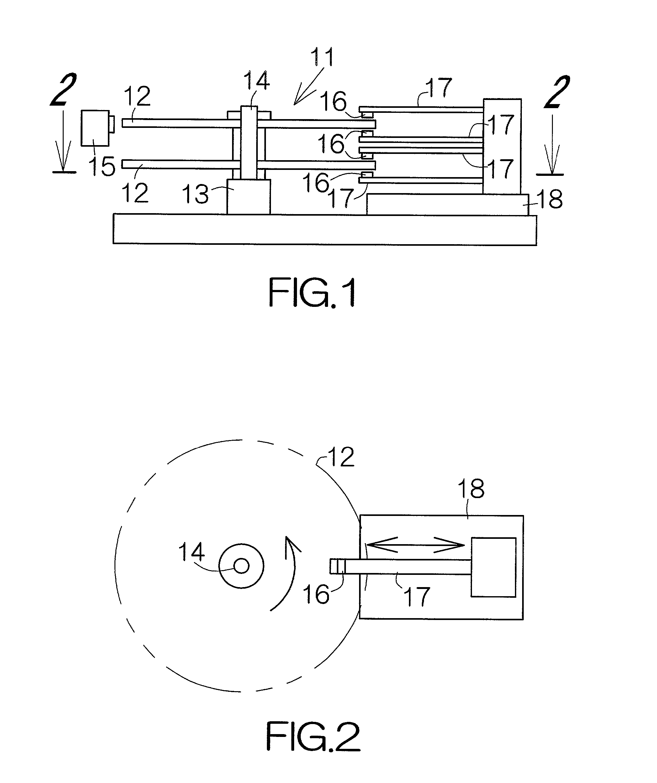
[0036]FIG. 1 schematically illustrates a writer of head positioning information, namely, a servo track writer 11. The servo track writer 11 includes a spindle motor 13 receiving one or more recording media such as magnetic recording disks 12, for example. The spindle motor 13 is designed to drive the magnetic recording disks 12 around a driving shaft 14. The respective magnetic recording disks 12 are allowed to rotate within parallel horizontal planes.

[0037]An eccentricity sensor 15 is connected to the driving shaft 14 of the spindle motor 13. The eccentricity sensor 15 is designed to detect the amount of eccentricity or vibration of the rotating driving shaft 14. The eccentricity sensor 15 may comprise a noncontacting vibration sensor such as a laser range finder, a capacitance type range finder, and the like. In this case, the eccentricity sensor 15 is designed to detect displacement amount of the magnetic recording disks 12 in parallel with the horizontal plane.

[0038]Flying head ...


PUM

PropertyMeasurementUnit
distanceaaaaaaaaaa
rotation speedaaaaaaaaaa
areaaaaaaaaaaa

Abstract

A writer for head positioning information, or a so-called servo track writer allows the read gap to follow a track which has been established on a recording medium or disk. As long as the read gap keeps following the existing track, the write gap is allowed to move along a path extending in parallel with the existing track. The write gap is utilized to write head positioning or servo information into the recording medium along the path. Even when the recording medium suffers from vibration or the like, the read gap can follow the track. The head positioning information can thus be written into the recording medium so as to establish a head positioning pattern at a higher positional accuracy.

Description

BACKGROUND OF THE INVENTION[0001]1. Field of the Invention[0002]The present invention relates to a recording medium such as a magnetic recording disk incorporated in a hard disk drive (HDD), for example. In particular, the invention relates to a writer or a method for writing head positioning or servo information into the recording medium.[0003]2. Description of the Prior Art[0004]A writing apparatus of head positioning information, such as a so-called servo track writer, is designed to utilize a magnetic head in writing head positioning or servo information into a magnetic recording disk. The magnetic head is usually mounted on a head slider. When the magnetic head finishes writing of the servo information for a single track, the head slider is forced to shift in the radial direction of the magnetic recording disk by a predetermined displacement amount. This movement serves to establish a predetermined interval or track pitch between adjacent tracks.[0005]When the servo information...

Claims


Application Information

Patent Timeline
Patent Type & Authority Patents(United States)
IPC IPC(8): G11B21/02G11B15/12G11B15/46G11B5/29G11B21/10G11B5/55G11B5/596
CPCG11B5/59633G11B5/5582G11B5/596
Inventor SUZUKI, HIROYUKIKOMORIYA, HITOSHINAKAMURA, YUTAKAHIRAHARA, TAKAO
Owner TOSHIBA STORAGE DEVICE CORP
Why Eureka
Try Eureka