Eccentricity control method for magnetic disk, recording medium recording eccentricity control method, and magnetic disk apparatus using eccentricity control method

Inactive Publication Date: 2006-03-14
PANASONIC CORP
View PDF11 Cites 12 Cited by
  • Summary
  • Abstract
  • Description
  • Claims
  • Application Information

AI Technical Summary

Benefits of technology

[0016]A recording medium which records a program of an eccentricity control method for magnetic disk according to the present invention records a program of an eccentricity control method for mag

Problems solved by technology

This results in a large amount of the multiplication and summation operation, and hence needs a large amount of time in the calculation.
The control delay due to the necessity of a large amount of time in the calculation causes directly an adverse effect to the control performance.
F

Method used


Image

  • Eccentricity control method for magnetic disk, recording medium recording eccentricity control method, and magnetic disk apparatus using eccentricity control method
  • Eccentricity control method for magnetic disk, recording medium recording eccentricity control method, and magnetic disk apparatus using eccentricity control method
  • Eccentricity control method for magnetic disk, recording medium recording eccentricity control method, and magnetic disk apparatus using eccentricity control method

Examples


first embodiment

[0055]A first embodiment of the invention is described below with reference to FIG. 1 through FIG. 3.

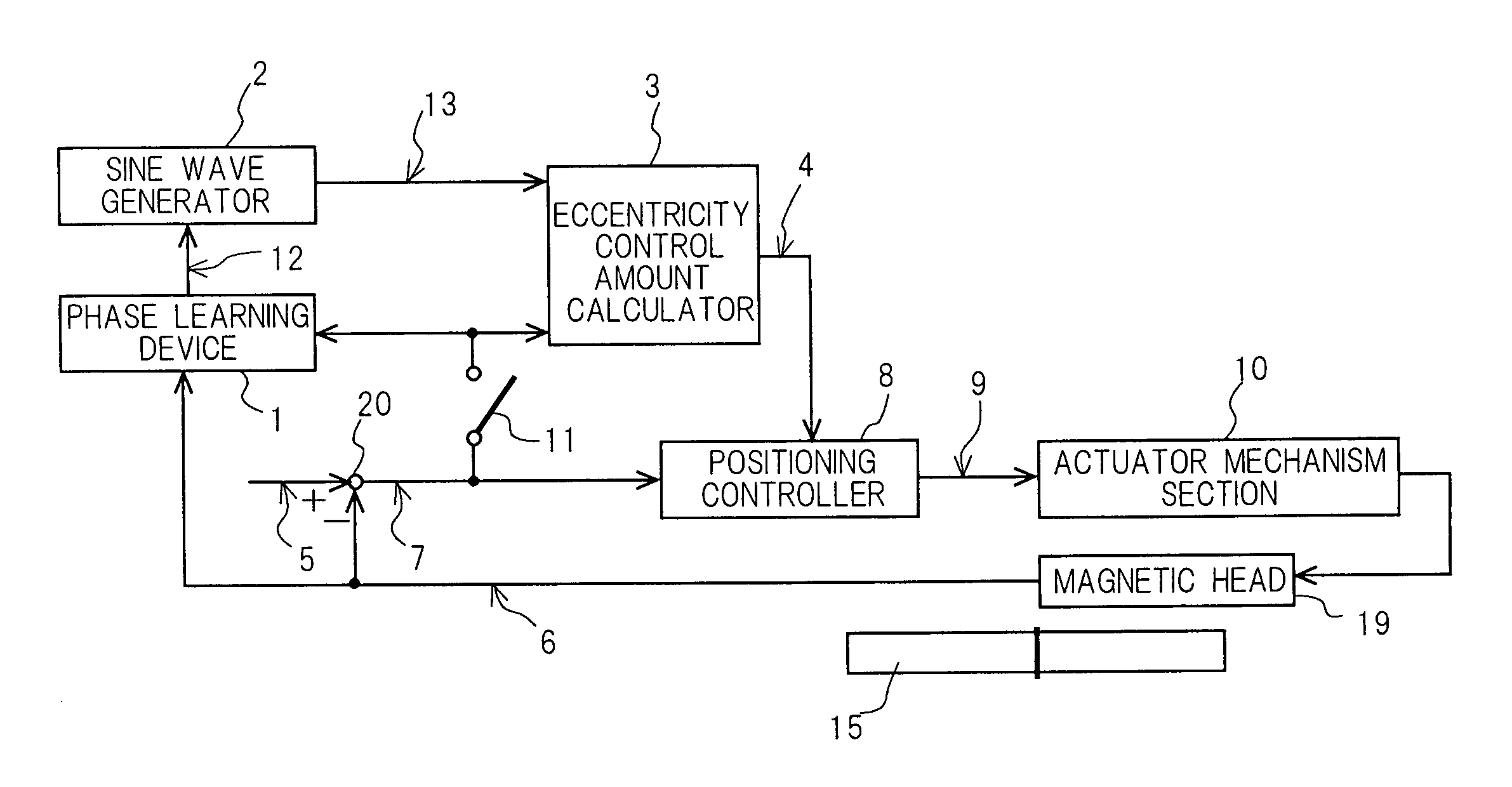
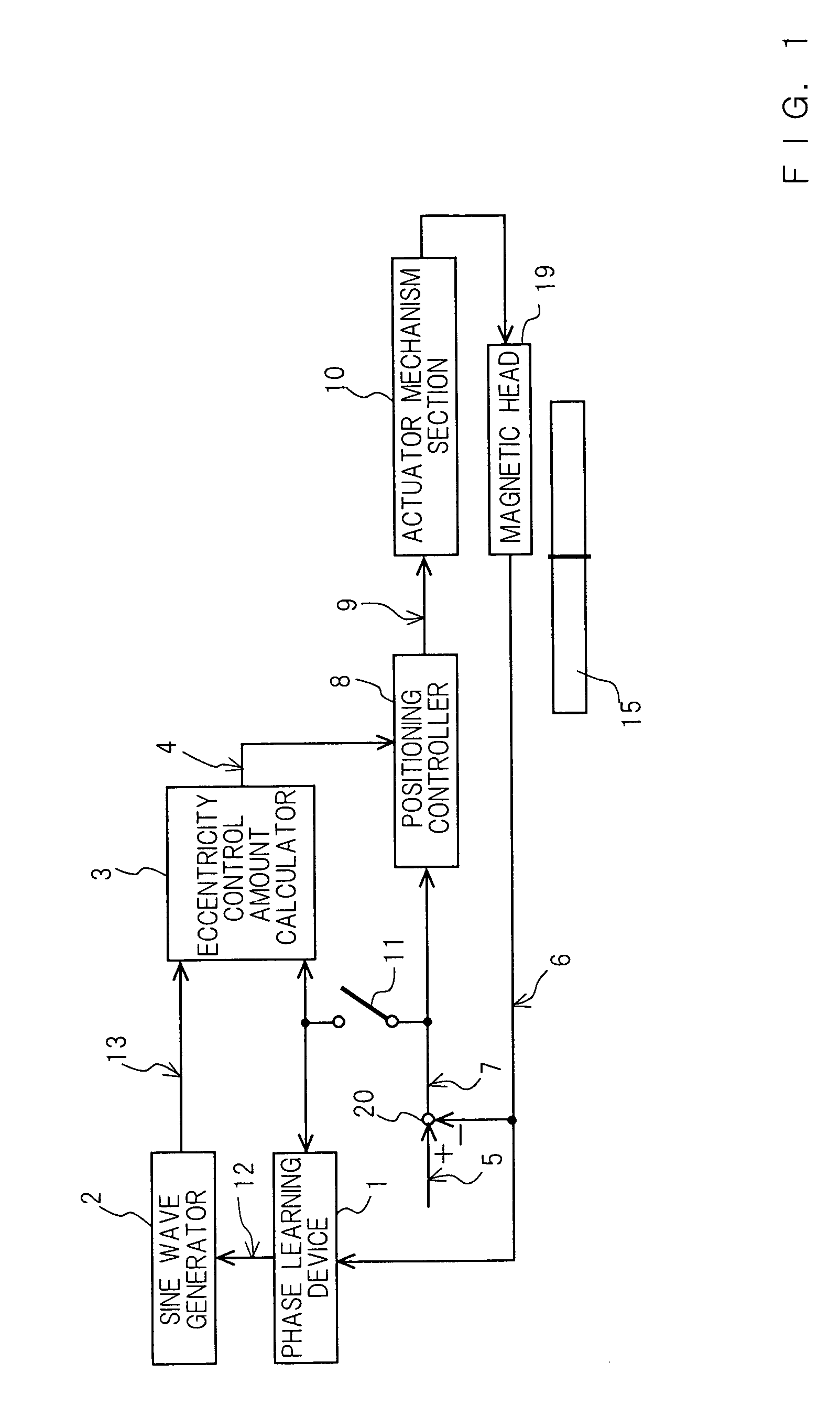
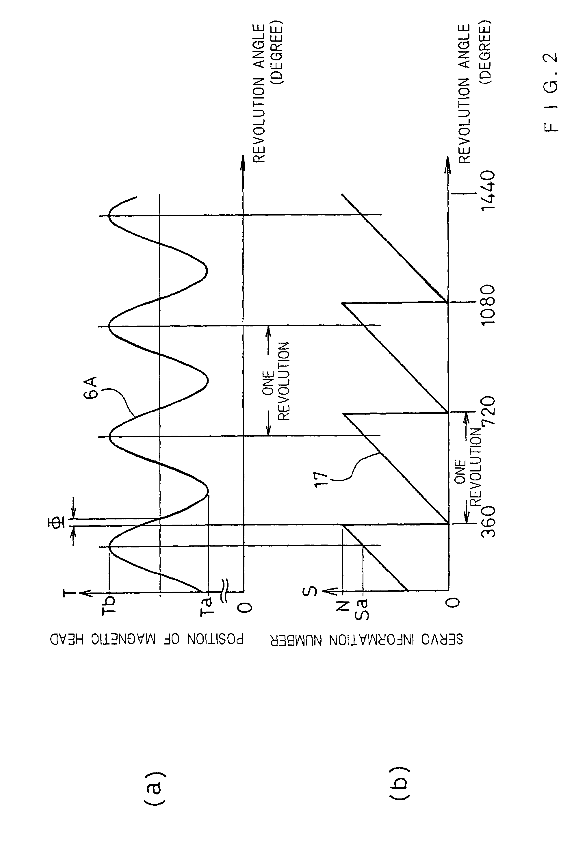
[0056]FIG. 1 is a block diagram showing a magnetic disk apparatus according to the invention. FIG. 2A is a graph of which the horizontal axis indicates the revolution angle (degree) of a magnetic disk, and the vertical axis indicates the position of a magnetic head, and FIG. 2B is a graph of which the horizontal axis indicates the revolution angle (degree) of the magnetic disk, and the vertical axis indicates a servo information number. FIG. 3A is a plan view showing a magnetic disk 15 having concentric tracks T0–Tn and servo information regions S0–SN, and FIG. 3B is an enlarged partial view of the magnetic disk 15 showing the tracks T0, T1, T2, . . . and the servo information regions S0–SN. In the following description, the tracks T0–Tn can be described as track numbers T0–Tn, and the servo information regions S0–SN can be described as servo information numbers S0–SN; that is, the s...

second embodiment

[0070]A second embodiment of the invention is described below with reference to FIG. 1, FIG. 4A, and FIG. 4B. The vertical axis of FIG. 4A indicates the position error of a magnetic head, while the horizontal axis indicates the revolution angle of the magnetic disk 15. The vertical axis of FIG. 4B indicates the servo information number, while the horizontal axis indicates the above-mentioned revolution angle.

[0071]FIG. 4A and FIG. 4B are diagrams showing the relations of the change of the position error of the magnetic head 19 and the change of the servo information number on the magnetic disk 15 in a magnetic disk apparatus according to the second embodiment of the invention. In the present embodiment, the position error E of the magnetic head 19 relative to a target track is obtained on the basis of the track number T. When the magnetic disk 15 is off-centered, the position error E varies in the form of a sine wave.

[0072]In the start-up of the magnetic disk apparatus, in the state...

third embodiment

[0081]A third embodiment of the present invention is described below with reference to FIG. 5 and FIG. 6.

[0082]FIG. 5 is a block diagram showing a magnetic head positioning control apparatus in a magnetic disk apparatus according to the third embodiment.

[0083]FIG. 6A is a diagram showing the change of the traveling speed of the magnetic head relative to the revolution angle of the magnetic disk in the magnetic disk apparatus according to the present embodiment, and FIG. 6B is a diagram showing the change of the servo information number.

[0084]In FIG. 5, the head position signal 6 outputted from the magnetic head 19 is subtracted from the target position signal 5 in the subtractor 20, whereby a position error signal 7 is outputted. The position error signal 7 is applied to the learning switch 11 and the positioning controller 8. The output of the positioning controller 8 is applied to the actuator mechanism section 10, whereby the actuator mechanism section 10 drives the magnetic head...


PUM


Abstract

In the start up of the magnetic disk apparatus, the phase relation between servo information numbers recorded on the magnetic disk 15 in advance and the eccentricity of the magnetic disk is learned. In the positioning of the magnetic head, a signal generated by multiplying, by a weight coefficient, a sine wave or a cosine wave the phase the revolution frequency of the magnetic disk is fed forward as an eccentricity control amount, whereby the eccentricity is compensated.

Description

CROSS-REFERENCE TO RELATED APPLICATION[0001]This application is a Section 371 of International Application No. PCT / JP02 / 10392, filed Oct. 4, 2002, the disclosure of which is incorporated herein by reference.TECHNICAL FIELD[0002]The present invention relates to an eccentricity control method for magnetic disk for causing a magnetic head to follow a target track of an off-centered magnetic disk, and a magnetic disk apparatus using this eccentricity control method.BACKGROUND ART[0003]In a magnetic disk apparatus,in order to perform recording and reproduction on a target track of an off-centered magnetic disk with a magnetic head, a magnetic head control apparatus is necessary for causing the magnetic head to follow the target track which varies continually in distance from a revolution center owing to the eccentricity. A conventional eccentricity control apparatus of a prior art magnetic head control apparatus comprises a sine wave and cosine wave generator, a digital Fourier transform...

Claims


Application Information

Patent Timeline
IPC IPC(8): G11B5/596G11B21/08G11B21/10
CPCG11B5/59627G11B21/08
Inventor SHIGEMATSU, NORIO
Owner PANASONIC CORP
Why Eureka
Try Eureka