Method for configuring a telecommunication system

Inactive Publication Date: 2006-03-14
MITSUBISHI ELECTRIC CORP
View PDF10 Cites 13 Cited by
  • Summary
  • Abstract
  • Description
  • Claims
  • Application Information

AI Technical Summary

Benefits of technology

[0090]means by which at least said second entity determines the variations between the number of output symbols from and the number of input symbols to said rate matching means starting from said first and second transmit

Problems solved by technology

But yet, in a CDMA type system, the capacity of the system is limited by the level of interference.
Thus, an increase in the energy of bits coded for a user (Eb) contributes to increasing interference (I) for other users.
This causes a problem, since rate matching ratios are defined identically at both ends of the radio link.
The quality of service is characterized in particular by a processing delay, a bit error rate and an error rate per block.
Therefore, it is understandable that transport channels with different qualities of service do not have the same needs in terms of the Eb/I ratio, and that if the rate is not matched, the quality of some transport channels would be “too” good since it is fixed by the most demanding channel and would unnecessarily cause interference on adjacent transport channels.
In the downlink, the peak/average ratio of the radio frequency power is not very good, since the network transmits to several users at the same time.
Signals sent to these users are combined constructively or destructively, thus inducing large variations in the radio frequency power emitted by the network, and therefore a bad peak/average ratio.
This discontinuous transmission degrades the peak/average ratio of the radio frequency power, but this degradation is tolerable considering the simplified construction of the receiving mobile station obtained with a semi-static rate matching ratio.
However, it introduces a number of problems as we will demonstrate.
1) nothing is written to say what is meant by the composite rate (the exact rate can only be determined when the variations ΔN have been calculated; therefore, it cannot be used in the calculation rule);
2) even if this concept were defined, it is probable that there are some cases in which the transport format combination that gives the maximum composite rate is n

Method used


Image

  • Method for configuring a telecommunication system
  • Method for configuring a telecommunication system
  • Method for configuring a telecommunication system

Examples


first embodiment

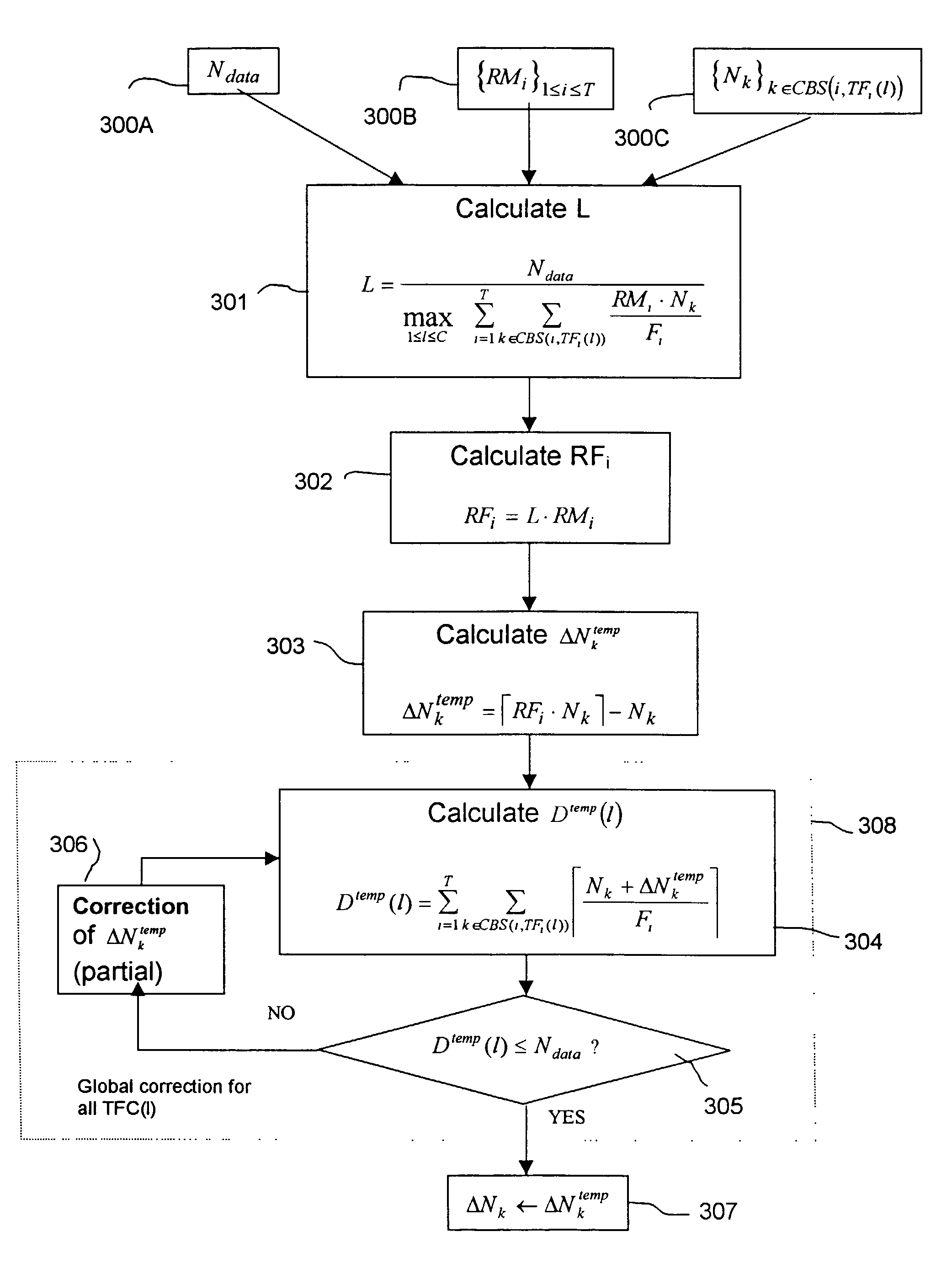
[0115]The member at the right of this equation is a rate estimator of the composite CCTrCH for the transport formats combination l. This equation (12) can then be used to find an approximate value of the factor L maximized under the constraint represented by equation (10) to satisfy equation (11). illustrated in FIG. 3, this value is given by the following equation: L=Ndatamax1≤l≤C⁢∑i=1i=T⁢∑k∈CBS⁡(i,TFi⁡(l))⁢RMi·NkFi(13)

[0116]Note that the denominator in the member at the right of equation (13) is the maximum value of the rate estimator of the composite CCTrCH for the transport format combinations and calculated assuming L=1 (which is equivalent to assume fictitiously that RF1=RMi).

[0117]This calculation step is denoted 301 in FIG. 3. Note that transmission of the Ndata parameter is referenced 300A in FIG. 3. Similarly, the transmission of parameters {RMi}l≦i≦T and the transmission of the numbers of symbols {Nk}kεCBS(i,TFi(l)) are denoted 300B and 300C respectively.

[0118]We then de...

third embodiment

[0128] illustrated in FIG. 5, the expression of the factor L is modified by using a coefficient that depends on known data (for example {RMi} or Ndata), in the numerator and in the denominator. This could have an impact on the calculated values to the extent that the expression of the factor L uses an approximation. For example, the following equation could be used: L=1LBASE·(min1≤i≤T⁢RMi)·⌊LBASE·(min1≤i≤T⁢RMi)·Ndatamax1≤l≤C⁢∑i=1T⁢∑k∈CBS⁡(i,TFi⁡(l))⁢RMi·NkFi⌋(13ter)

[0129]The rate matching ratios RFi are then calculated using equation (5) or (5bis).

[0130]In summary, the phase in which the temporary variations ΔNktemp are calculated comprises the following steps:[0131]1. Calculate the factor L as a function of the maximum physical rate Ndata and the RMi parameters (step 301, 401 or 501).[0132]2. Calculate the rate matching ratio RFi for each coded transport channel i, as a function of the RMi parameters and the factor L (step 302, 402 or 502).[0133]3. For each k type coded block in a ...


PUM


Abstract

A method and system for configuring a CDMA telecommunication system having at least one sending entity and at least one receiving entity, each entity configured to transmit data on at least one physical channel (DPDCH) via a transport channel composite (CCTrCH) of multiple transport channels. At least one entity includes a data processing module configured to determine for each transport channel a first parameter (RMi) proportional to a rate matching ratio (RFi) and a second parameter representing a maximum physical bit rate (Ndata) and to transform for each of the transport channels a number of symbols before rate matching (Nk) into a number of symbols after rate matching (Nk+ΔNk), where the number of symbols after rate matching (Nk+ΔNk) is obtained approximately by multiplying the number of symbols before rate matching (Nk) by the rate matching ratio (RFi).

Description

CROSS REFERENCE TO RELATED APPLICATION[0001]This application is a continuation of and claims the benefit of the earlier filing date of U.S. patent application Ser. No. 09 / 641,918, filed on Aug. 21, 2000 now U.S. Pat. No. 6,510,137.FIELD OF INVENTION[0002]This invention relates to a method for configuring a telecommunication system comprising at least one sending entity and at least one receiving entity, said sending and receiving entities implementing a step for transmission of data transported on at least one physical channel, said at least one physical channel transmitting a transport channel composite under formation and having its own maximum physical rate, said transport channel composite comprising at least two transport channels, said data transmission step being preceded by a data processing procedure for each of said transport channels, said data processing procedure comprising at least one rate matching step, said rate matching step transforming a number of symbols before ...

Claims


Application Information

Patent Timeline
IPC IPC(8): H04L12/26H04B1/69H04B7/26H04L1/00H04M1/725H04Q7/36H04Q7/38
CPCH04B7/264H04L1/0002H04L1/0017H04L1/0068H04L1/0041H04L1/0067H04L1/0025H04L1/0038
Inventor BELAICHE, VINCENT ANTOINE VICTOR
Owner MITSUBISHI ELECTRIC CORP
Why Eureka
Try Eureka