Communication system using optical fibers

a technology of optical fiber and communication system, applied in the field of communication system, can solve the problem of limited subscriber capacity of indoor radio system, and achieve the effect of increasing the subscriber capacity

Active Publication Date: 2006-03-14
NTT DOCOMO INC
View PDF16 Cites 138 Cited by
  • Summary
  • Abstract
  • Description
  • Claims
  • Application Information

AI Technical Summary

Benefits of technology

[0010]It is therefore an object of the present invention to provide increased subscriber capacity in a communication system that has plural radio access units connected to optical fibers used as basic transmission lines.

Problems solved by technology

On this account, the subscriber capacity of the indoor radio system is limited as compared with an outdoor radio system.

Method used


Image

  • Communication system using optical fibers
  • Communication system using optical fibers
  • Communication system using optical fibers

Examples


embodiment 1

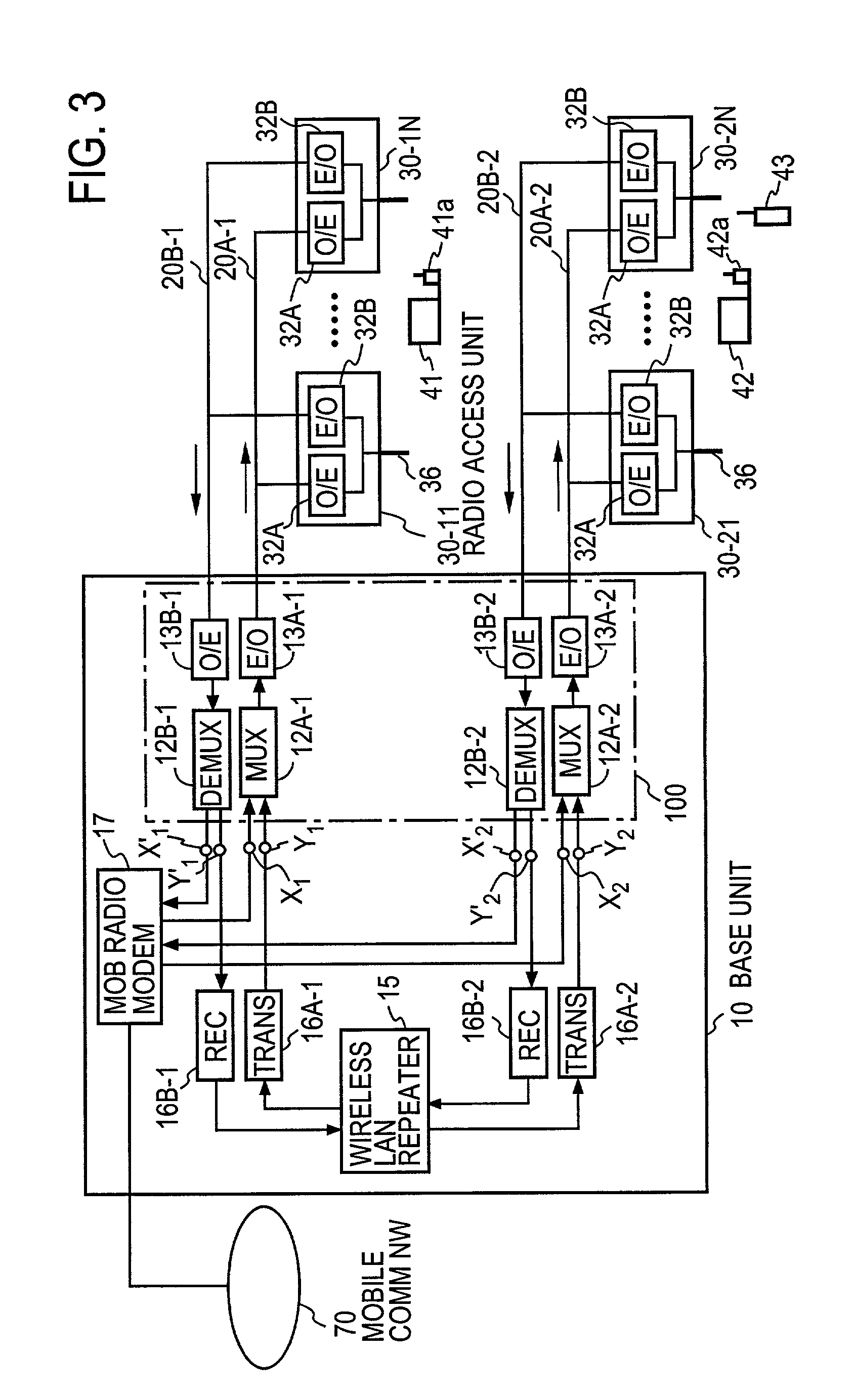
[0038]FIG. 3 illustrates in block form a first embodiment of the present invention. According to this embodiment, in a divider / combiner unit 100, high-frequency signal of a mobile communication and a wireless LAN are multiplexed and then converted from electrical to optical form, thereafter being sent to radio access units over the same optical fiber; in this way, the mobile communication system and the wireless LAN system are implemented on the same communication system. This communication system has high cost-performance for the utilization of hybrid systems.

[0039]As depicted in FIG. 3, the communication system comprises: a center node (hereinafter referred to as a base unit) 10; radio access units 30-11 to 30-1N and 30-21 to 30-2N (hereinafter identified by 30); wireless LAN system terminals 41 and 42; radio channel access units 41a and 42a; a mobile terminal 43 connectable to a mobile communication network (which terminal will hereinafter be referred to as a mobile communication...

embodiment 2

[0056]FIG. 4 illustrates in block form a second embodiment of the communication system of the present invention. This embodiment is a modified form of the FIG. 3 embodiment, in which the wireless LAN system is adapted to be connectable to the Internet (an IP network). In the wireless LAN system in FIG. 4, the wireless LAN repeater 15 in the base unit 10 has a function of connection to an external communication network such, for example, as an IP network 80. This embodiment is exactly identical in construction with the FIG. 3 embodiment except the above.

[0057]That is, the incorporation of an Internet protocol in the wireless LAN repeater 15 enables the wireless LAN system terminal to be easily connected to the IP network, making it possible to receive communication services such as an access to the Internet and a file transfer. Accordingly, such a wireless LAN system offers a radio network environment equivalent to a wired one, hence providing increased mobility of users.

[0058]In the...

embodiment 3

[0059]FIG. 5 illustrates in block form a third embodiment of the communication system according to the present invention. This embodiment of another modified form of the FIG. 3 embodiment, in which the wireless LAN system is adapted to be connectable to the mobile communication network by protocol conversion. In the wireless LAN system of this embodiment the base unit 10 is further provided with a protocol converter 101 and a combiner / separator 102. Since the wireless LAN system and the mobile communication system use different communication protocols, the protocol converter 101 converts the communication protocol of the former to the communication protocol of that of the latter. The combiner / separator 102 combines the signal of the protocol converted by the protocol converter 101 with a signal from the mobile radio modem 17, then connects the combined signal to the mobile communication network 70. And at the same time it separates the signal addressed to the wireless LAN repeater 1...


PUM


Abstract

A divider/combiner unit combines RF signals, then converts the combined signal into an optical signal and sends it over an optical fiber. N radio access units each convert the optical signal received from the optical fiber into an RF signal and transmits it from an antenna, and each radio access unit converts an RF signal received by the antenna into an optical signal and sends it over an optical fiber to the divider/combiner unit. The divider/combiner unit converts the received optical signal into RF signals and outputs them. This system is operated as plurality of communication systems in common to them in correspondence to a plurality of input/output terminals of the divider/combiner unit.

Description

BACKGROUND OF THE INVENTION[0001]The present invention relates to a communication system having radio access units connected to optical fibers.[0002]Conventionally, a wireless local area network (LAN) is used indoors for radio communications between computer terminals. The wireless LAN involves no wire connection of a terminal to a LAN connecting port, and hence it provides greater flexibility in the placement of terminals than does LAN that requires wire connection between computer terminals.[0003]The wireless LANs known so far are, for example, a radio system in the unlicensed ISM (Industrial Scientific and Medical) band at 2.4 GHz using a spread spectrum scheme, a radio channel access method using OFDM (Orthogonal Frequency Division Multiplexing) scheme at 5 GHz according to IEEE802.11 and IEEE1394, and the Buletooth (short distance radio communication scheme) using the spread spectrum scheme based on the frequency hopping system.[0004]These wireless LANs mostly employ such a sta...

Claims


Application Information

Patent Timeline
Patent Type & Authority Patents(United States)
IPC IPC(8): H04B10/00H04B10/24H04B7/00H04J14/00H04B10/2575
CPCH04B10/25755
Inventor SUZUKI, YASUNORICHEN, NINGTARUSAWA, YOSHIAKINOJIMA, TOSHIO
Owner NTT DOCOMO INC
Why Eureka
Try Eureka