Methods and apparatus for calculating routing arrangements for control cables

Inactive Publication Date: 2006-03-14
CHUO SPRING
View PDF9 Cites 6 Cited by
  • Summary
  • Abstract
  • Description
  • Claims
  • Application Information

AI Technical Summary

Benefits of technology

[0024]After the intermediate clamped part is modeled and the routing arrangement for the control cable is calculated, whether the position of the clamping point is appropriate or not may be determined based upon a distance between the calculated routing arrangement and the clamping point. For instance, if there is a great distance between the calculated r

Problems solved by technology

However, it is difficult to predict the routing arrangement for the control cable from a degree of deformability (a degree of freedom of the routing arrangement) of the control cable.
Therefore, in order to determi

Method used


Image

  • Methods and apparatus for calculating routing arrangements for control cables
  • Methods and apparatus for calculating routing arrangements for control cables
  • Methods and apparatus for calculating routing arrangements for control cables

Examples


first representative embodiment

(First Representative Embodiment)

[0074]A representative embodiment of an apparatus for calculating routing arrangements for control cables will hereinafter be described. First, control cable 50 to be analyzed will be briefly explained with reference to FIGS. 15 and 16.

[0075]As shown in FIG. 15, control cable 50 includes outer cable 54 and inner cable 52, which is inserted within outer cable 54.

[0076]Outer cable 54 is a cylindrical hollow member. As clearly shown in FIG. 16, sleeve 62 is connected to each end of outer cable 54 via connector 56 swinguably (movably around a central point). Sealing member 64 and cushioning member 66 are disposed on an outer surface of connector 56. Outer cover 58 is fitted on an outer surface of sealing member 64 and an outer surface of cushioning member 66. Outer covers 58 on both ends of outer cable 54 are respectively affixed to, for example, mounting grooves, one of which is formed in a housing of an input side apparatus and the other of which is fo...

second representative embodiment

(Second Representative Embodiment)

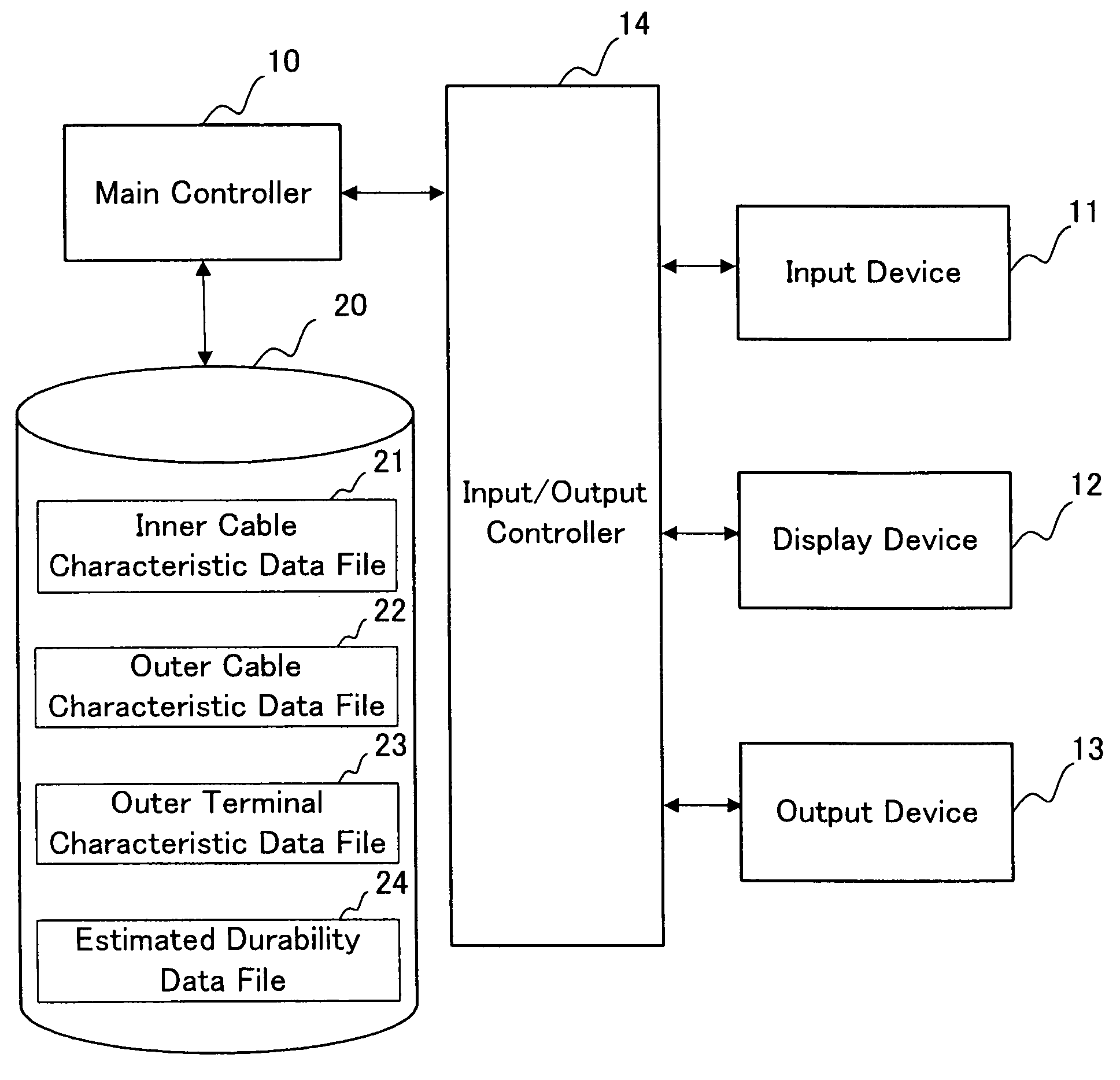
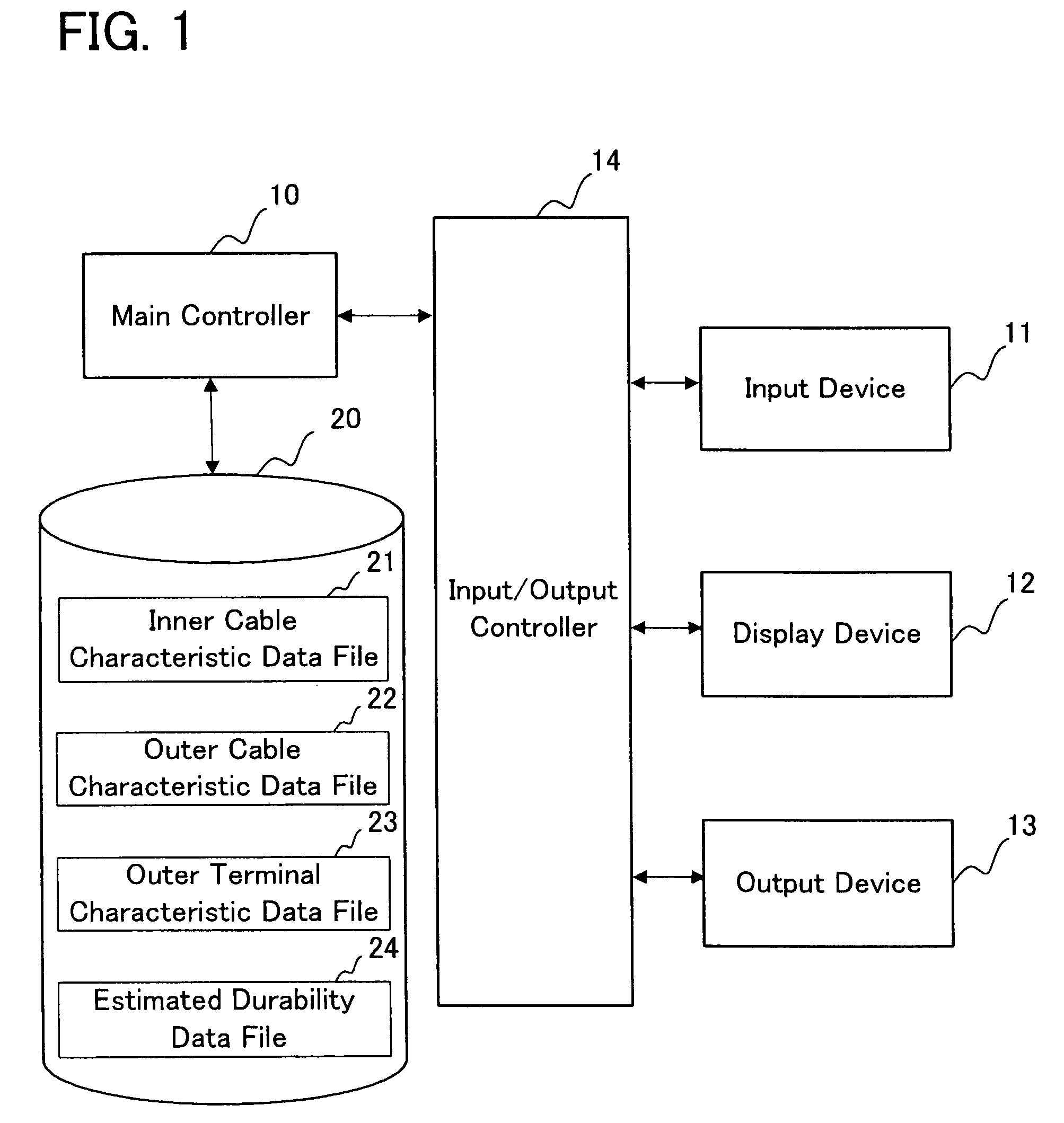
[0159]A cable routing arrangement calculation apparatus according to the second representative embodiment will now be described with reference to FIG. 31. FIG. 31 is a hardware configuration diagram of a routing arrangement calculation apparatus according to the second representative embodiment.

[0160]In the cable routing arrangement calculation apparatus of the second representative embodiment, the basic structure (e.g. a process for calculating a cable routing arrangement, a process for determining characteristics of a control cable, the contents of each of files that are held in a database) is the same as the basic structure of the cable routing arrangement calculation apparatus of the first representative embodiment, which was illustrated above. The features of the second representative embodiment, which are different from those of the first representative embodiment, are: (1) the cable routing arrangement calculation apparatus is connected to a ...


PUM


Abstract

The present invention provides a method for predicting a routing arrangement for control cable without preparing experimental control cables. In the method according to the present invention, characteristics of a control cable to be laid are obtained (S1, S2, and S3). The characteristics of the control cable can be obtained by subjecting a test piece of control cable to a known test (tensile test). Next, a length of the control cable and a condition for connecting the control cable are provided as conditions for a computation (S4 and S5). Then, the given length of the cable, the given condition for connecting the cable, and the obtained characteristic of the control cable are used for a computation model, which was formed by dividing the control cable into a plurality of elements, in order to perform a finite element method, and, thus, a routing arrangement is calculated (S7).

Description

FIELD OF THE INVENTION[0001]The present invention relates to control cables that transmit an input of a manipulating force, which an input side apparatus receives, to an output side apparatus, and more particularly it relates to techniques for estimating routing arrangements for the control cables that are disposed between the input side apparatus and the output side apparatus.BACKGROUND ART[0002]Known control cables include an outer cable and an inner cable, which is inserted within the outer cable. The inner cable can be axially moved by being guided along the outer cable.[0003]One end of the outer cable is affixed to a housing of an input side apparatus. The other end of the outer cable is affixed to a housing of an output side apparatus. In addition, one end of the inner cable is affixed to a manipulation member (e.g., a manipulation lever) of the input side apparatus. The other end of the inner cable is affixed to a transmission-receiving member (a member to which movement of t...

Claims


Application Information

Patent Timeline
IPC IPC(8): G01R31/02G06F17/50
CPCG06F17/5018G06F17/5095G06F2217/36G06F30/15G06F30/23G06F2113/16
Inventor NONO, KAZUYOSHITSUGE, YOSHIKATSUASHIKAWA, TAKAYUKIMISAKI, YOSHIOWAKITA, MASAMI
Owner CHUO SPRING
Why Eureka
Try Eureka