System and method for controlling the temperature and infrared signature of an engine

a technology of infrared signature and engine, which is applied in the direction of machines/engines, marine propulsion, vessel construction, etc., can solve the problems of limiting the cooling effect of air on engine components and limiting the reducing effect of air on aircraft's infrared signature, so as to reduce the infrared signature of engines

Active Publication Date: 2006-03-21
THE BOEING CO
View PDF6 Cites 33 Cited by
  • Summary
  • Abstract
  • Description
  • Claims
  • Application Information

AI Technical Summary

Benefits of technology

[0008]The present invention provides a system and method for cooling at least a portion of an engine and controlling the infrared signature of the engine. According to one present invention, the fuel used for combustion in the engine is also used to cool one or more hot components in the engine. For example, the fuel may be utilized to cool the exhaust nozzle and thus reduce the infrared signature of the engine.

Problems solved by technology

Typically, the air in the bypass duct reaches a temperature of between about 500° F. and 600° F., thereby limiting the cooling effect of the air on the engine components, especially near the nozzle, and limiting the reducing effect of the air on the aircraft's infrared signature.

Method used


Image

  • System and method for controlling the temperature and infrared signature of an engine
  • System and method for controlling the temperature and infrared signature of an engine
  • System and method for controlling the temperature and infrared signature of an engine

Examples


Embodiment Construction

[0020]The present invention now will be described more fully hereinafter with reference to the accompanying drawings, in which some, but not all embodiments of the invention are shown. Indeed, this invention may be embodied in many different forms and should not be construed as limited to the embodiments set forth herein; rather, these embodiments are provided so that this disclosure will satisfy applicable legal requirements. Like numbers refer to like elements throughout.

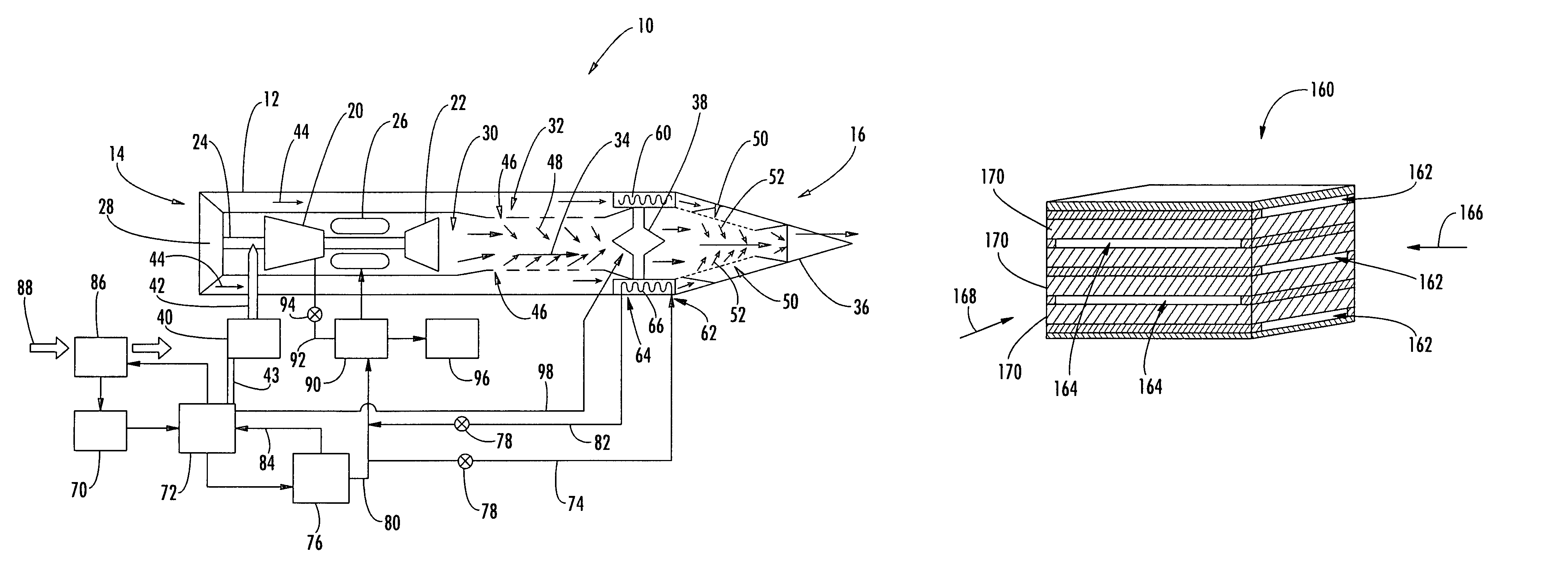
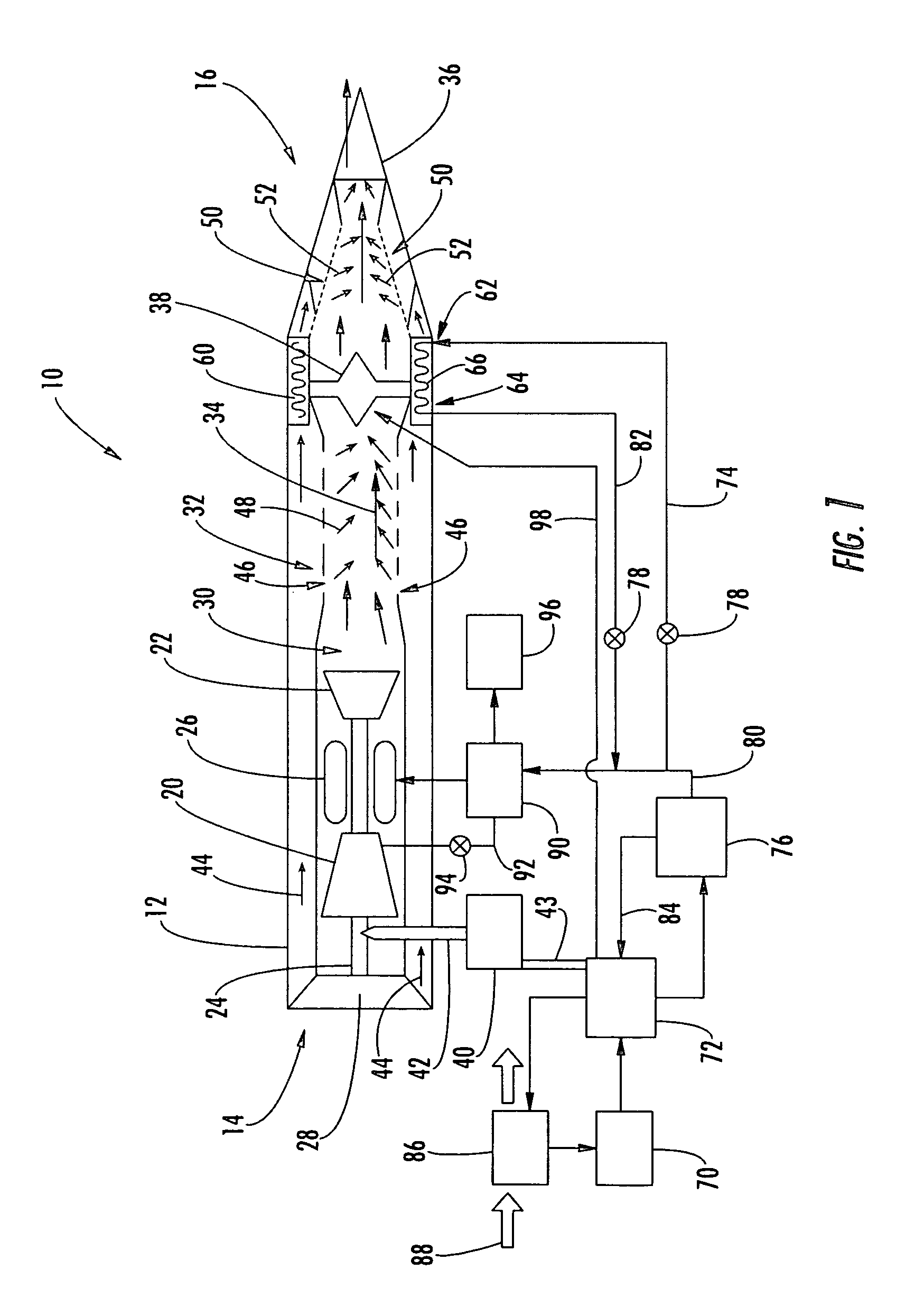
[0021]Referring now to the figures and in particular to FIG. 1, there is shown a turbine engine 10 according to one embodiment of the present invention. While the engine 10 is described herein primarily as a thrust generation device for an aircraft, it is understood that the engine can alternatively be used for other applications such as for powering other vehicles. The engine 10 includes a housing 12 extending from an inlet side 14 to an outlet side 16 and defining an engine passage therebetween. More particularl...


PUM


Abstract

A system and method for cooling at least a portion of an engine are provided. The engine is cooled using a fuel, such as a high heat sink fuel, that is subsequently used for combustion in the engine. The fuel can be used to cool one or more of the gases and / or components in the engine, thereby cooling the engine including an exhaust nozzle. For example, the fuel can be circulated through one or more heat exchanging devices that are disposed inside or outside a passage of the engine, and the fuel can absorb thermal energy from the engine or air that flows in the engine passage. In any case, the cooling of the engine can result in a reduction to the infrared signature of the engine.

Description

FEDERALLY SPONSORED RESEARCH OR DEVELOPMENT[0001]This invention was made with Government support under contract number F33615-99-D-2952 awarded by the U.S. Air Force. The government has certain rights in this invention.BACKGROUND OF THE INVENTION[0002]1) Field of the Invention[0003]The present invention relates to the control of temperature in an engine and, more particularly, to the use of fuel for cooling engine components and especially an exhaust nozzle such as in an aircraft engine.[0004]2) Description of Related Art[0005]Infrared emissions from aircraft, ships, tanks, other vehicles and structures, and the like provide an “infrared signature” that generally increases as the temperature of the components and exhausts of those devices increase. For example, the exhaust nozzle of a turbine engine of an aircraft receives the hot exhaust gases from the engine and can operate at temperatures in excess of 1000° F. Thus, the nozzle can emit significant infrared energy, thereby contrib...

Claims


Application Information

Patent Timeline
Patent Type & Authority Patents(United States)
IPC IPC(8): F02K3/06F02K1/44F02K1/82
CPCF02K1/822Y02T50/675Y02T50/60
Inventor IYA, SRIDHAR K.ROE, GEORGE M.
Owner THE BOEING CO
Why Eureka
Try Eureka