Control method and control apparatus of automatic transmission

a control method and automatic transmission technology, applied in the direction of gearing control, gearing elements, belts/chains/gearrings, etc., can solve the problem that the driver or the like may be given a feeling of wrongness, and achieve the effect of avoiding the interruption of the drive torque during shifting and not impairing the shift quality

Inactive Publication Date: 2006-03-21
HITACHI LTD +1
View PDF8 Cites 7 Cited by
  • Summary
  • Abstract
  • Description
  • Claims
  • Application Information

AI Technical Summary

Benefits of technology

[0012]Therefore the interruption of the drive torque duri...

Problems solved by technology

However, since the conventional automatic MT makes interruption of the drive torque occur by the clutch disengaging...

Method used


Image

  • Control method and control apparatus of automatic transmission
  • Control method and control apparatus of automatic transmission
  • Control method and control apparatus of automatic transmission

Examples


Embodiment Construction

Description of the Preferred Embodiments

[0032]The constitution and control method for the control apparatus of the automatic transmission of an embodiment of the present invention will be explained hereunder by referring to FIGS. 1 to 18.

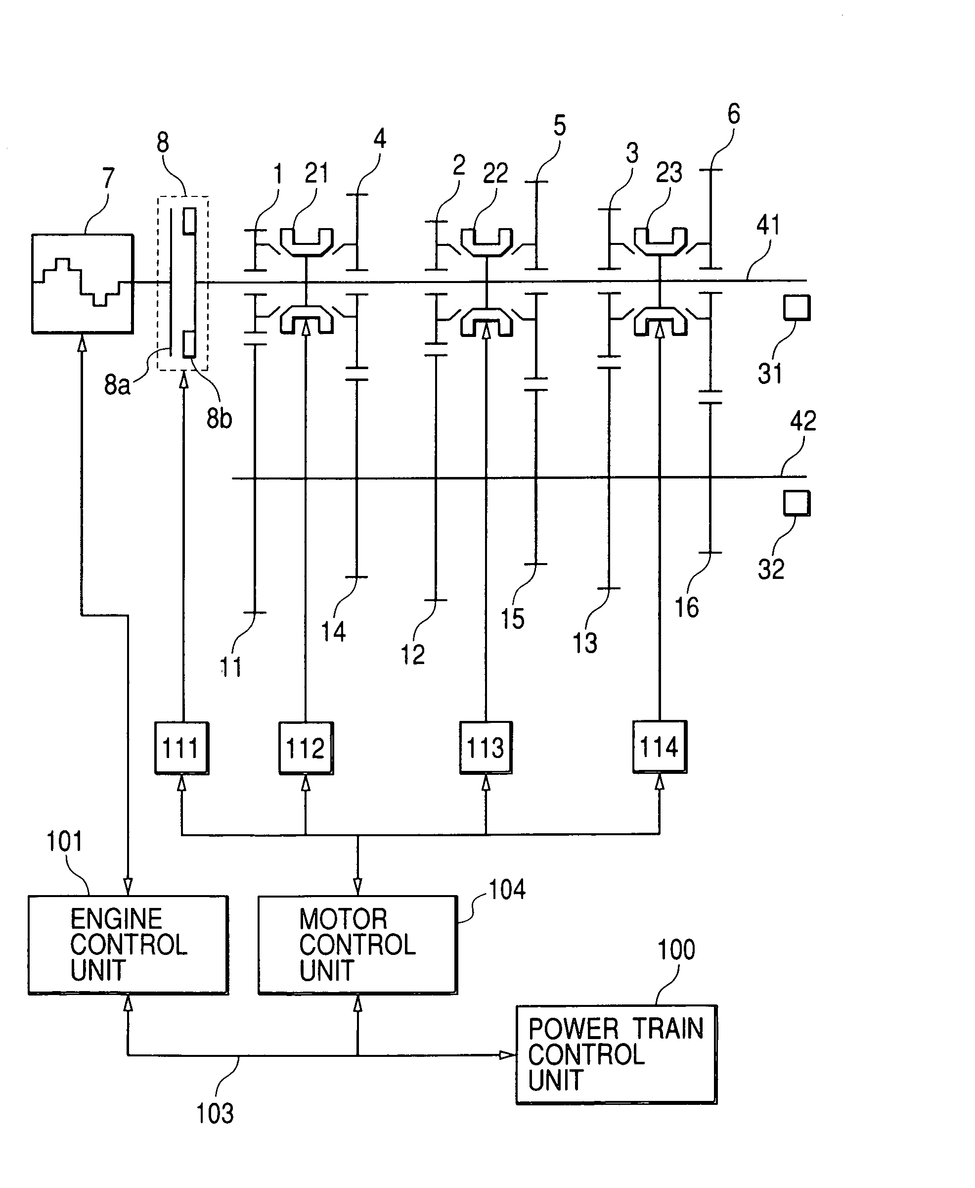
[0033]Firstly, the constitution of the control apparatus of the automatic transmission of this embodiment will be explained by referring to FIG. 1.

[0034]FIG. 1 is a skeleton diagram showing the constitution of the control apparatus of the automatic transmission of the embodiment.

[0035]An engine 7 which is a drive power source has an engine-speed sensor (not shown in the drawing) for measuring the speed of the engine 7, an electronic throttle (not shown in the drawing) for regulating the engine torque, and a fuel injection apparatus (not shown in the drawing) for injecting the amount of fuel corresponding to the amount of intake air. An engine control unit 101 operates the amount of intake air, the amount of fuel, and the ignition time, thereby can c...


PUM


Abstract

When shifting the gear position into a target gear position from a current gear position, some gear position different from said current gear position is used as one distributing gear position. The control unit controls the pressing load of a synchromesh of one distributing gear position to make at least part of the rotation torque from the drive power source transfer by the friction. Thereby it makes at least part of the rotation torque transferred by a synchromesh of the current gear position decrease. And then it moves the synchromesh of said current gear position to a disengaging position not meshed with said idle gear. Thereafter another gear position different from said target gear position and said one distributing gear position is used as another distributing gear position. So that it controls the pressing load of the synchromesh of another distributing gear to make the transfer torque increase gradually by the friction, and simultaneously makes the pressing load of the synchromesh of one distributing gear position decrease gradually. Besides such a distribution of transfer torque, it makes the speed of said input shaft synchronize with the speed corresponding to said target gear position by controlling the speed of said input shaft, and then moves the synchromesh of the target gear position to the meshing position.

Description

FIELD OF THE INVENTION[0001]The present invention relates to a control method and a control apparatus of an automatic transmission, and more particularly to a control method and a control apparatus suitable for controlling a synchromesh type automatic transmission used for a car.PRIOR ART[0002]In recent years, an automatic manual transmission (hereinafter, referred to as an “automatic MT”), which is a system automating a clutch and a gear change machinery by applying a synchromesh type transmission used for a manual transmission, has been developed. However, since the conventional automatic MT makes interruption of the drive torque occur by the clutch disengaging and engaging operation under control at the time of shifting, the driver or the like may be given a feeling of wrongness.[0003]Therefore, for example, as described in U.S. Pat. No. 2,703,169, a friction type assist clutch is installed in a automatic MT, and the drive torque is transferred by the assist clutch during shiftin...

Claims


Application Information

Patent Timeline
IPC IPC(8): F16H59/00F16H61/04F16H61/682
CPCF16H61/0403F16H61/682F16H2061/0418Y10T74/19251Y10T477/60Y10T477/6939F16H2306/48
Inventor MATSUMURA, TETSUOOKADA, TAKASHISAKAMOTO, HIROSHIISHIHARA, SUNAOSUNAGA, ISAMUKUMAGAI, TOSHIHARU
Owner HITACHI LTD
Why Eureka
Try Eureka