Fuel injector control system

Active Publication Date: 2006-03-21
CATERPILLAR INC
View PDF12 Cites 51 Cited by
  • Summary
  • Abstract
  • Description
  • Claims
  • Application Information

AI Technical Summary

Benefits of technology

[0006]One aspect of the present disclosure is directed to a control system for a fuel injector. The control system includes a valve element movable between a first position and a second position, and an armature connected to the valve element. The control system includes a solenoid configured to move the armature and connected valve, and a controller in communication with the solenoid. The controller is configured to energize the solenoid at a first current level to initiate movement of the valve element from the first position toward the second position, thereby initiating an injection of fuel. The controller is also configured to energ

Problems solved by technology

Although the solenoid control circuit of the '878 patent may sufficiently inject fuel into an engine, it may do little to minimize bouncing of the control valve and the resulting effects.
In particular, due to inertia of the moving control valve and the associated fuel, upon fully opening, the control valve may tend to bounce away from an upper seat, thereby adversely affecting fuel delivery characteristics.
Because the hold-in current of the '878 patent is single tiered, it may be insufficient

Method used


Image

  • Fuel injector control system
  • Fuel injector control system
  • Fuel injector control system

Examples


Embodiment Construction

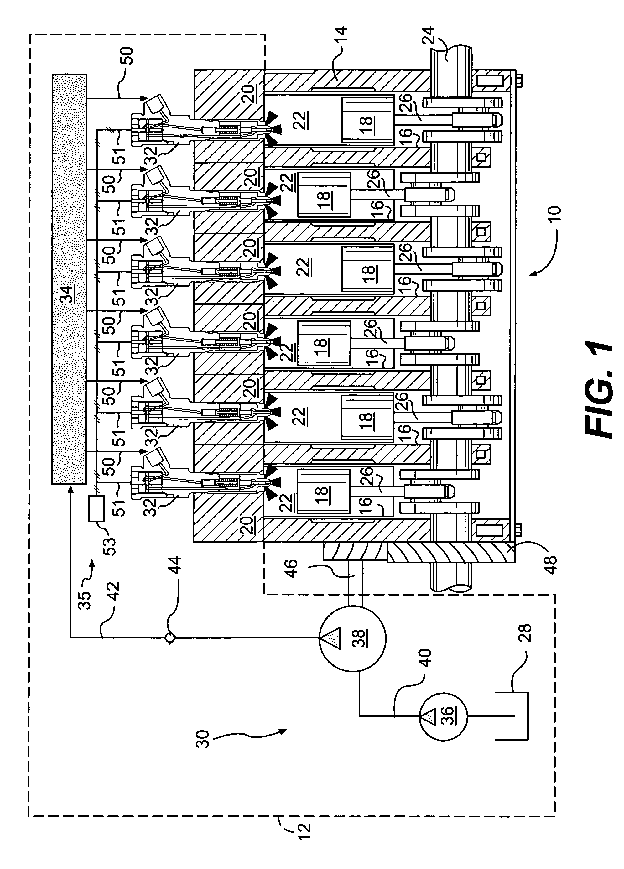
[0014]FIG. 1 illustrates an engine 10 and an exemplary embodiment of a fuel system 12. For the purposes of this disclosure, engine 10 is depicted and described as a four-stroke diesel engine. One skilled in the art will recognize, however, that engine 10 may be any other type of internal combustion engine such as, for example, a gasoline or a gaseous fuel-powered engine. Engine 10 may include an engine block 14 that defines a plurality of cylinders 16, a piston 18 slidably disposed within each cylinder 16, and a cylinder head 20 associated with each cylinder 16.

[0015]Cylinder 16, piston 18, and cylinder head 20 may form a combustion chamber 22. In the illustrated embodiment, engine 10 includes six combustion chambers 22. However, it is contemplated that engine 10 may include a greater or lesser number of combustion chambers 22 and that combustion chambers 22 may be disposed in an “in-line” configuration, a “V” configuration, or any other suitable configuration.

[0016]As also shown in...


PUM


Abstract

A control system for a fuel injector is disclosed. The control system has a valve element movable between a first position and a second position, an armature connected to the valve element, a solenoid configured to move the armature and connected valve element, and a controller in communication the solenoid. The controller is configured to energize the solenoid at a first current level to initiate movement of the valve element from the first position toward the second position, at a second current level less than the first current level during movement of the valve element from the first position toward the second position, at a third current level less than the second current level after the valve element has reached the second position, and at a fourth current level less than the third current level after the valve element has been in the second position for a predetermined period of time.

Description

TECHNICAL FIELD[0001]The present disclosure is directed to a control system and, more particularly, to a control system for a fuel injector.BACKGROUND[0002]Common rail fuel injectors provide a way to introduce fuel into the combustion chamber of an engine. Typical common rail fuel injectors include an actuating solenoid that opens a fuel injector nozzle when the solenoid is energized. Fuel is then injected into the combustion chamber as a function of the time period during which the solenoid remains energized. Accurate control of both the delivery timing and duration of fuel is important to engine performance and emissions.[0003]To optimize engine performance and emissions, engine manufacturers may vary the times when the solenoid is energized and de-energized, as well as the magnitude of the current applied to the solenoid. One such example is described in U.S. Pat. No. 4,922,878 (the '878 patent) issued to Shinogle et al. on May 8, 1990. The '878 patent describes a solenoid contro...

Claims


Application Information

Patent Timeline
IPC IPC(8): F02M51/00
CPCF02D41/20F02D2041/2006F02D2041/2041F02D2041/2037F02D2041/2017
Inventor PUCKETT, DANIEL R.LOVE, W. JOHN
Owner CATERPILLAR INC
Why Eureka
Try Eureka