Key pad, resin key top injection mold, and resin key top manufacturing method

a manufacturing method and key pad technology, applied in the field of key pad, resin key top injection mold, and resin key top manufacturing method, can solve the problems of insufficient illumination of resin key tops, inability to uniformly and sufficiently illuminate all resin key tops, etc., and achieve the effect of avoiding light leakage and not easily detached from the apparatus

Inactive Publication Date: 2006-03-21
POLYMATECH CO LTD
View PDF12 Cites 27 Cited by
  • Summary
  • Abstract
  • Description
  • Claims
  • Application Information

AI Technical Summary

Benefits of technology

[0009]As described above, the present invention has been made after examining the way to avoid the problem of contact involved when the conventional key pad 1 is to be reduced in thickness and size. It is accordingly an object of the present invention to provide a key pad for use in a portable electronic apparatus or the like in which the resin key tops and the chip components such as LEDs do not come into contact with each other, which eliminates light leakage at the time of illumination, and in which the resin key tops are not easily detached from the apparatus.
[0012]In accordance with this invention, the resin key tops have in their side surfaces clearance portions of a configuration in conformity with the outer configuration of interference members at least the upper portions of which are situated in displacement regions at the bottom surface edges of the resin key tops allowing their displacement when they are depressed, so that the resin key tops do not come into contact with the interference members whether the key tops are being depressed for input operation or not being depressed. Thus, it is possible to cope with the reduction in the distance between the side surfaces of the resin key tops and the reduction in the vertical distance between the resin key tops and the substrate due to the reduction in thickness and size. In particular, in the case of a key pad in which the resin key tops have on their side surfaces outwardly protruding flange portions with clearance portions formed therein, there is practically no fear of light being leaked through the gaps between the apparatus casing and the resin key tops when the back lights are on. Thus, such a resin key top with a clearance portion is capable of coping with a reduction in the thickness and size of the apparatus and is optimally applicable to an illumination type key pad and resin key tops used therein.
[0017]In this resin key top injection mold, the runner portion communicating with the key top forming portion is provided in the cavity. Further, in the cavity, there is provided the resin relief protrusion having a molding surface swollen from the entrance of the key top forming portion and the runner portion toward the key top forming portion, with the molding surface being smaller in width than the entrance and of a configuration in conformity with the outer configuration of the interference member at least the upper portion of which is situated in the displacement region of the bottom surface edge of the resin key top to be displaced upon a depressing operation. Thus, solely by the runner portion cutting off process, it is possible to easily form a clearance portion of a configuration in conformity with the outer configuration of the interference member, which is of, e.g., a V-shaped or arcuate configuration, on the resin key top and a part of the flange portion thereof. Further, since the resin relief protrusion is smaller in width than the entrance, it is possible for a molten resin to flow without allowing any air to be gathered on either side of the resin relief protrusion, making it possible to obtain a resin key top superior in dimensional performance and quality and a key pad using the same.
[0018]Further, this injection mold can be formed as one with pin holes allowing detachable attachment of a plurality of pin members constituting resin relief protrusions and differing in molding surface configuration. By thus forming pin holes allowing detachable attachment of a plurality of pin members differing in molding surface configuration, quick adaptation to a product with an interference member having a different outer surface configuration is possible solely by replacing the pin members without involving any remodeling of the mold itself, making it possible to obtain a resin key top injection mold superior in product compatibility.
[0019]Further, in a resin key top injection mold the entrance of which is wider on the key top forming portion side and narrower on the runner portion side, flow of a molten resin into the cavity takes place quickly, and it is possible to reduce or eliminate an occurrence of air gathering. Further, in a resin key top injection mold with an air vent portion communicating with a part of the runner portion, it is possible to eliminate any generation of flow marks on the resin key tops.
[0021]In this resin key top manufacturing method, it is possible to easily form a clearance portion of a configuration in conformity with the outer configuration of the interference member on a part of the flange portion through a normally conducted runner portion eliminating process without adding any surplus step to the conventional resin key top manufacturing process. Further, since a molten resin is poured into the cavity of the injection mold having the runner portion and the resin relief protrusion, the clearance portion formed on the resin key top through molding can be reliably in a configuration in conformity with the outer configuration of the accommodating portion of the key sheet and no defective molding due to an occurrence of gathering of air or the like is involved. Further, generation of flow marks on the resin key top is prevented, and it is possible to obtain a high quality resin key top in which, even if an indicating portion having a character, symbol or the like thereon is provided on the back side of the resin key top, the indicating portion is not distorted by flow marks.

Problems solved by technology

However, that would result in some of the resin key tops 3 not being sufficiently illuminated, making it impossible to uniformly and sufficiently illuminate all the resin key tops 3.
However, that would involve a deterioration in the depression-operability of the resin key tops 3, resulting in a rather inaccurate input operation, which is inconvenient for the user.
However, as shown in FIG. 13, with the method in which the flange portions 8 are partially trimmed by a trimming die after the molding of the resin key tops 3, the cutting edges a through c are likely to involve positional variation, so that the width dimensions of the remaining flange portions 8 are rather varied, resulting in frequent occurrence of light leakage at the time of illumination.

Method used


Image

  • Key pad, resin key top injection mold, and resin key top manufacturing method
  • Key pad, resin key top injection mold, and resin key top manufacturing method
  • Key pad, resin key top injection mold, and resin key top manufacturing method

Examples


example 1

[0061]As the mold for molding the resin key tops (13) of polycarbonate resin for a mobile phone, the first mold (31) of hard iron for molding the front side of the resin key tops (13) and the second mold (32) of hard iron for molding the back side of the resin key tops (13) were prepared, as shown in FIGS. 5 and 6. When mated with each other, the first mold (31) and the second mold (32) define the cavity composed of the key top forming portion (34) having in the outer periphery of the lower end of the side surface thereof an outwardly protruding flange portion (39), the first runner portion (33), and the second runner portion (35). Further, the molding pin (41) of hard iron was inserted into the pin insertion hole (42) of the first mold to thereby form inside the cavity the column-like resin relief protrusion (38).

[0062]Molten polycarbonate resin was injected into the cavity through the resin injection hole (36) of the second mold (32), and after its solidification, the resin was re...

example 2

[0065]Instead of the mold used in Example 1, a mold (not shown), which differs from in a point that it had a resin relief protrusion on the first runner portion side and had no resin relief protrusion on the second runner portion side, was used to form a polycarbonate resin key top (13) in the same manner as in Embodiment 1.

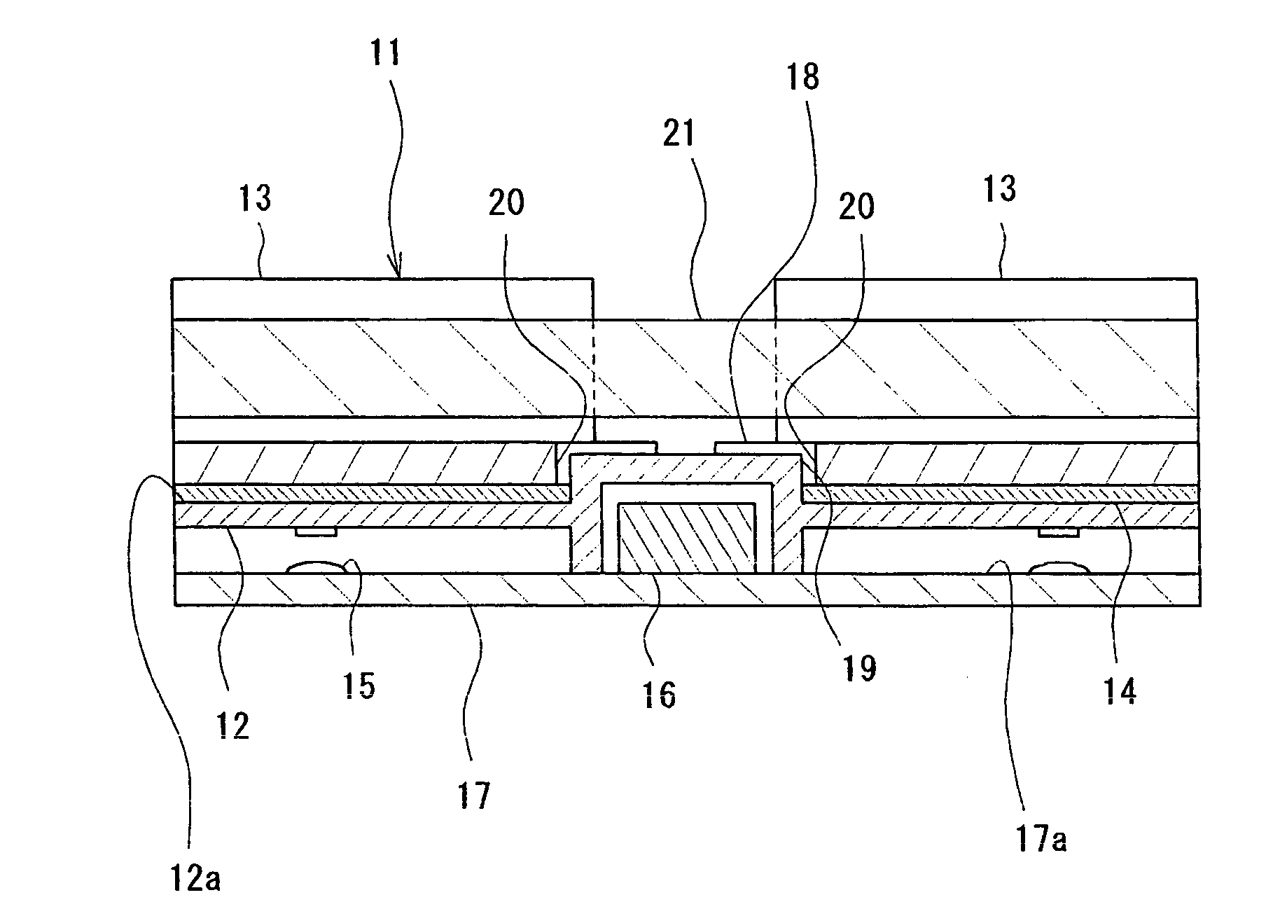
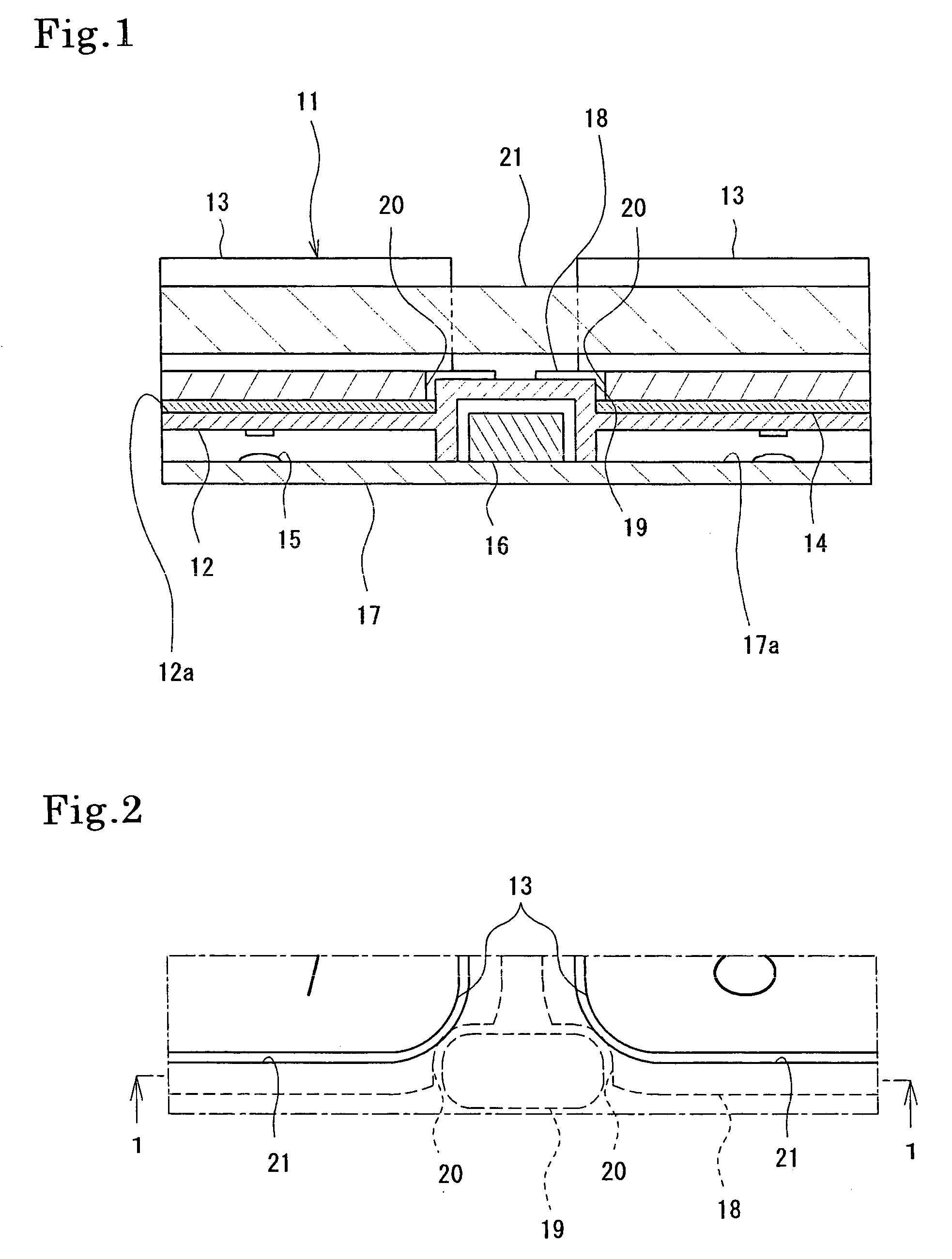
[0066]As in Example 1, according to this method of manufacturing the resin key top (13), the resin key top (13) with the clearance portion (20) could be easily obtained solely by cutting off the portions corresponding to the first runner portion and the second runner portion by using the cutting die. However, some flow marks, which are seemingly attributable to the flow of molten polycarbonate resin from the first runner portion provided with the resin relief protrusion to the key top forming portion, were observed on the flange portion (18) and other portions of the resin key top (13).


PUM

PropertyMeasurementUnit
thicknessaaaaaaaaaa
heightaaaaaaaaaa
heightaaaaaaaaaa

Abstract

A key pad has resin key tops on a key sheet. The resin key tops have in their side surfaces clearance portions of a configuration in conformity with an outer configuration of interference members at least an upper portions of which are situated in displacement regions at bottom surface edges of the resin key tops allowing their displacement when they are depressed.

Description

BACKGROUND OF THE INVENTION[0001]1. Field of the Invention[0002]This invention relates to a key pad suitable as a push-button switch component to be incorporated in the input portion of an electronic apparatus, such as a telephone, an audio apparatus, a television set, a VCR, a facsimile apparatus, a copying machine, or a vehicle-mounted apparatus, and, in particular, to a key pad, which is suitable as the push-button switch component of a portable apparatus of which a reduction in thickness and size is required. Further, this invention relates to a resin key top injection mold and a resin key top manufacturing method.[0003]2. Related Background Art[0004]Up to now, an illumination type key pad equipped with a translucent elastic key sheet and a translucent resin key top has been widely used as a push-button switch component to be incorporated in the input portion of a portable apparatus, such as a mobile phone. FIG. 12 shows a specific example of such a key pad. In the drawing, a ke...

Claims


Application Information

Patent Timeline
Patent Type & Authority Patents(United States)
IPC IPC(8): B41J5/08B41J5/10H01H9/18H01H13/14H01H11/00H01H13/02H01H13/702
CPCH01H13/702H01H2229/044H01H2227/036H01H2219/014
Inventor YAMAUCHI, MOTOSHI
Owner POLYMATECH CO LTD
Why Eureka
Try Eureka