Printer and paper feed controller

a controller and printer technology, applied in the field of printer and paper feed controller, can solve the problems of high-resolution encoder system used in industrial applications, unsuitable for general applications that need low-cost printers, difficult resolution improvement, etc., and achieve the effect of high feeding resolution

Inactive Publication Date: 2006-03-21
CANON KK
View PDF6 Cites 26 Cited by
  • Summary
  • Abstract
  • Description
  • Claims
  • Application Information

AI Technical Summary

Benefits of technology

[0023]In view of the above, it is an object of the present invention to provide a paper feed controller and a printer using a paper feed controller, capable of precisely feeding paper with a high feeding resolution.

Problems solved by technology

Regarding the increase in resolution of the encoder, a high-resolution encoder system used in industrial applications is expensive and thus unsuitable for use in general applications that need low-cost printers.
However, to improve the paper feed resolution of the conventional printer, many problems must be solved.
Regarding the reduction in the nozzle pitch of the print head, the reduction is limited by limitations on the head design and production techniques and the upper limit of cost, and thus the improvement in resolution is not easy (in particular, the improvement needs a very large increase in cost).
In the technique of determining the stop position such that the distance to the next stop position becomes equal to a common multiple of the minimum paper feeding unit and the nozzle pitch of the print head, the paper feeding distance does not have a simple value (deviated from 2 raised to nth power) and thus a complicated calculation is needed in image processing.
This can cause a reduction in performance of the print head.
A further problem of this technique is that a restriction is imposed on the design of the diameter of the paper feed roller and the diameter of the encoder wheel.
However, in this technique, the resolution is limited to 2 raised to nth power such as 1200 dpi, 2400 dpi, 4800 dpi and so on.
On the other hand, to increase the amount of information obtained very shortly before the stop position, it is needed to increase the size of the encoder wheel connected to the paper feed roller, which results in an increase in the total size of the printer.
Besides, if the amount of information is increased, it becomes necessary to process the large amount of information, which can cause an increase in processing time and a reduction in throughput.
This can make it impossible to obtain information necessary in a low-velocity region very shortly before the paper feed roller is stopped.
The lack of a sufficient amount of information makes it impossible to precisely determine the velocity immediately before the stop position and thus the stop position accuracy becomes low.
In such a situation, the accuracy of the calculated velocity becomes low.
Thus, controlling of the feeding of paper in the very low velocity range is difficult.
This makes it difficult to precisely control the stop position.
However, although high accuracy twice that obtained in the previous example is achieved, the diameter of the encoder wheel becomes twice as large as that in the previous example, and thus it becomes difficult to achieve a small total size.
Besides, the encoder wheel cannot be rotated at a high speed unless the sensor has a correspondingly high response speed.
However, in this technique, the maximum stop position error is not guaranteed, and thus this technique cannot be used when high stop position accuracy is required and the maximum stop position error must be guaranteed.
In general, because the velocity in the low velocity range is calculated based on a small number of encoder pulses, it is difficult to achieve high accuracy in the calculated velocity.
Besides, the velocity can fluctuate due to a disturbance such as mechanical friction, a back tension of paper, a fluctuation of a driving force transmission load, or cogging of a motor.
In practice, as described above, in the above-described technique of turning off the electric power to the motor at the time calculated based on the velocity calculated at the position the predetermined distance before the target stop position, it is difficult to precisely calculate the timing of turning off the electric power to the motor.
Besides, a varying deviation of the stop position from the target stop position occurs after the electric power to the motor is turned off, owing to a disturbance before the paper feed roller stops, such as the back tension of paper, the fluctuation of the driving force transmission load, or cogging of the motor.

Method used


Image

  • Printer and paper feed controller
  • Printer and paper feed controller
  • Printer and paper feed controller

Examples


first embodiment

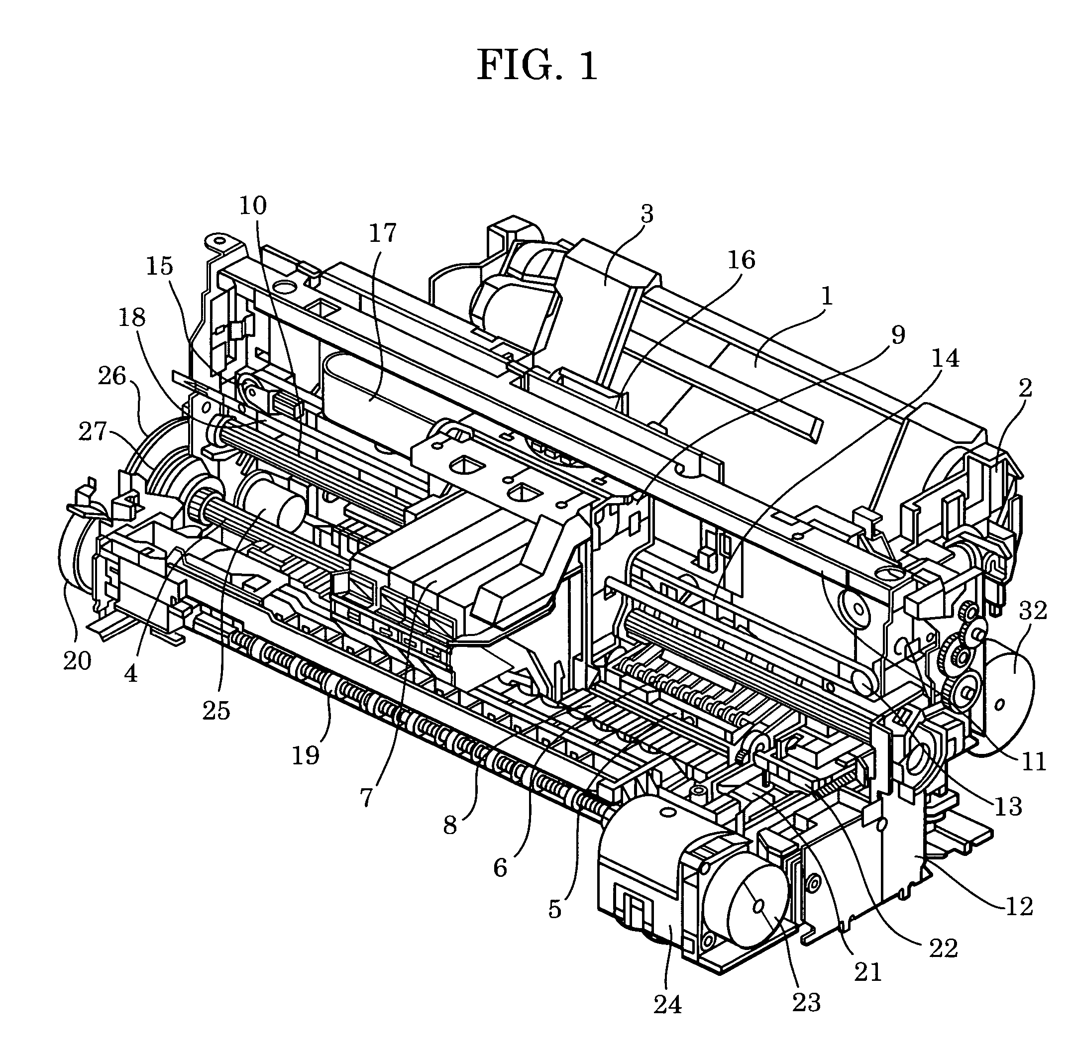
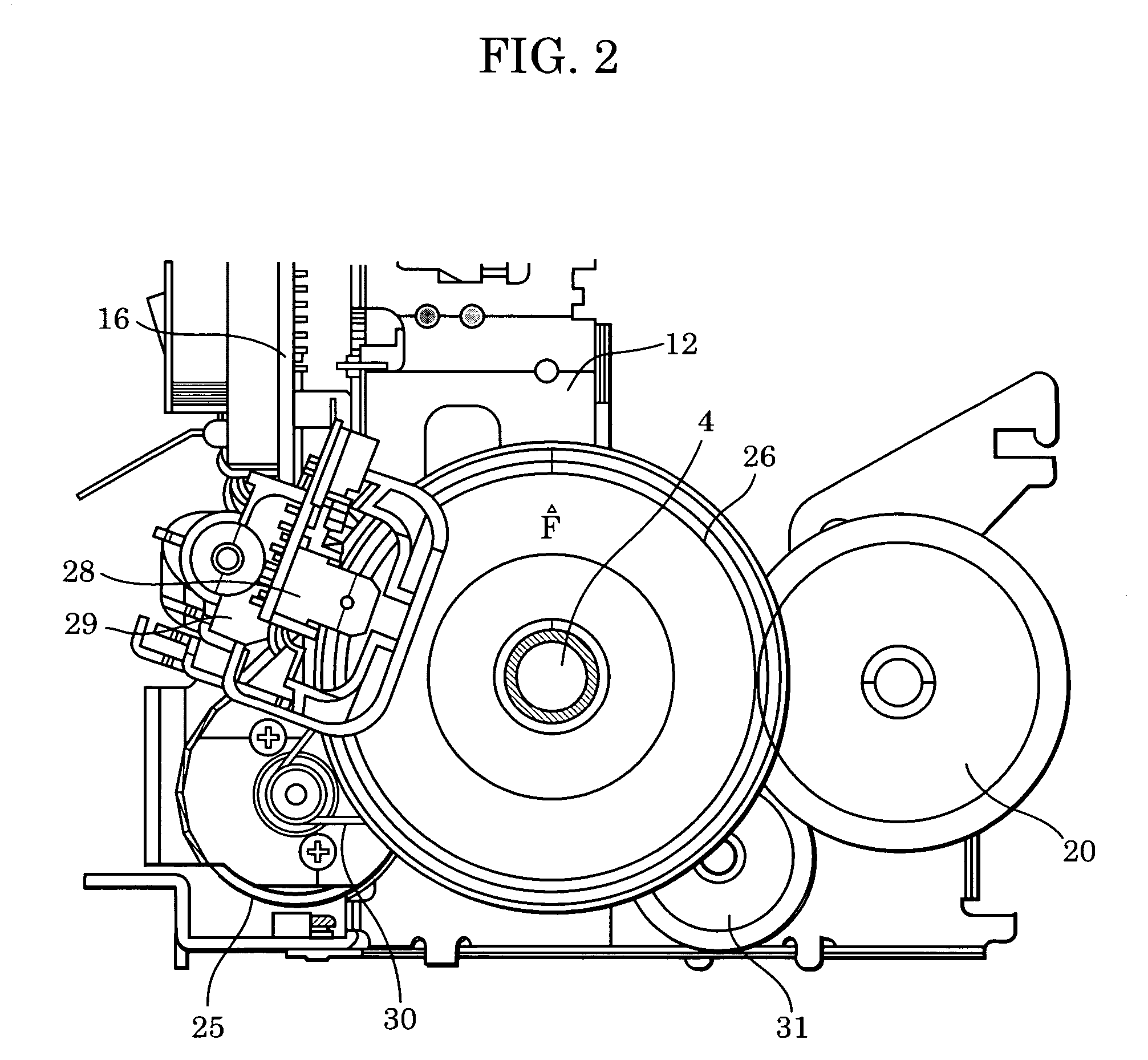
[0040]FIG. 1 is a general perspective view of a printer, and FIG. 2 is a side view of a paper feeding system.

[0041]The printer includes an automatic document feeder, a paper transport mechanism, a paper ejection unit, a carriage unit, and a cleaning unit. The outline of each of these parts is described below.

(A) Automatic Document Feeder

[0042]The automatic document feeder includes a platen 1 on which to place a stack of paper P and a base 2 having a paper feed roller (not shown) for feeding paper P. A movable side guide 3 is movably disposed on the platen 1 so that the movable side guide 3 defines the position at which the stack of paper P is placed. The platen 1 is rotatable about a shaft connected to the base 2 and is urged against the paper feed roller by a platen spring (not shown).

[0043]Some sheets of paper P are fed by the driving force of a paper feed motor 32 to a nip part formed by the paper feed roller and a separation roller (not shown). The sheets of paper P are separate...

second embodiment

[0109]A second embodiment is described below with reference to FIG. 13C.

[0110]Herein, only different points from those of the first embodiment are described.

[0111]In this second embodiment, as shown in FIG. 13C, unlike the first embodiment, the stop operation is performed at a position (timing) that does not correspond to any edge of the encoder signal but that is determined by using a falling edge of phase B as a reference point, and a rising edge of phase A is used as E1 (assurance edge).

[0112]This operation mode is useful in particular when the calculation velocity has a large error and the stop operation is often performed at the assurance edge E1. In this operation mode, at a position (timing) corresponding to an edge of the encoder signal shown in FIG. 13B, the stop signal for the stop operation is output exactly at the edge (a rising edge of phase A). This makes it possible to minimize the difference in stop position accuracy between the on-edge stop operation mode and the no...

third embodiment

[0117]A third embodiment of the present invention is described below. A printer according to the third embodiment has a similar structure to that of the first embodiment, and thus a duplicated description of the structure is not given herein. The present embodiment is different from the first embodiment in terms of the following points.

[0118]In FIG. 12, 1200 shows an operation in a situation in which the actual velocity is equal to the velocity V0, and 1201 shows an operation in a situation in which the actual velocity is higher than the velocity V0. In the case of 1201, before the time calculated based on the velocity V0 has elapsed, the paper reaches the edge E1 appearing immediately after the target stop position (the result of step 1105 becomes YES).

[0119]When the paper reaches a position corresponding to the edge E1 after the target stop position is passed over, the stop operation is performed (step 1107) by changing the electric power supplied to the motor to a level that is o...


PUM


Abstract

High accuracy is achieved in paper feed control without increasing the size of an encoder, which would result in an increase in cost. The velocity of a paper feeding mechanism is calculated from an edge signal that is generated by the encoder in response to the motion of the paper feeding mechanism. Based on the calculated velocity, a calculation is performed as to the time needed to reach a stop position since a detection of an encoder signal edge immediately before the stop position. Based on the calculated time, a control signal for stopping the paper feeding mechanism is generated.

Description

[0001]This application claims priority from Japanese Patent Application No. 2003-372458 filed Oct. 31, 2003, which is hereby incorporated by reference herein.BACKGROUND OF THE INVENTION[0002]1. Field of the Invention[0003]The present invention relates to a printer using a print head and a paper feed controller for controlling paper feed means for feeding a printing medium such as printing paper.[0004]2. Description of the Related Art[0005]In recent years, a great advance has been made in terms of image quality of an ink-jet printer. However, there is a continuing need for a further improvement in resolution which is one of factors of image quality. In a serial-type ink-jet printer, a carriage including a print head is scanned across a printing medium (hereinafter, also referred to as printing paper or simply as paper) while emitting ink with well controlled timing thereby forming an image. Each time the carriage is scanned across the paper, the paper is fed a predetermined distance....

Claims


Application Information

Patent Timeline
Patent Type & Authority Patents(United States)
IPC IPC(8): B41J11/42B41J2/01B41J11/00B41J19/20
CPCB41J11/0095B41J19/202B41J11/42
Inventor SAITO, HIROYUKISHOJI, MICHIHARU
Owner CANON KK
Why Eureka
Try Eureka