Clamping and adjustment apparatus for a cutting tool

a technology of clamping adjustment and cutting tool, which is applied in the direction of turning apparatus, milling cutter, milling equipment, etc., to achieve the effect of limiting the setting range of the clamping adjustment apparatus, reducing the deflection of the tension screw, and enlarge the adjustment rang

Active Publication Date: 2006-03-21
GUHRING JORG
View PDF32 Cites 39 Cited by
  • Summary
  • Abstract
  • Description
  • Claims
  • Application Information

AI Technical Summary

Benefits of technology

[0030]In cutting inserts which have no slant or an opposite slant of the lateral wall abutting on the adjustment wedge with respect to the direction of the desired cutter adjustment, on the other hand a convex arrangement of the adjustment and the actuation wedge on the double wedge pin is advantageous. The pressure exerted by the pressure screw leads to a displacement of the adjustment wedge in the displacement direction determined by the wedge receptacle and thus to a pressure against the wall of the cutting insert so that in turn a radial excursion of the cutting insert occurs.
[0031]Particularly in a double wedge pin having concavely arranged wedge surfaces, it is advantageous if an ejection spring is provided which enables non-problematic removal of the double wedge pin when taking apart the tool.
[0032]A further aspect of the invention concerns a tool in which a tension screw is used for prestressing and fastening the cutting insert. In the adjustment apparatus according to the invention as well as in known adjustment apparatuses, a force arises through the excursion occurring during the adjustm

Problems solved by technology

Due to manufacturing tolerances in the cutter support as well as in the cutting insert, wear during operation, etc., it is

Method used


Image

  • Clamping and adjustment apparatus for a cutting tool
  • Clamping and adjustment apparatus for a cutting tool
  • Clamping and adjustment apparatus for a cutting tool

Examples


Embodiment Construction

[0073]In the following description of preferred embodiments of the invention, functionally identical or similar features in the shown embodiments were given similar reference numbers in order to ensure better clarity. In order to avoid repetitions, features of embodiments which are identical to those in the preceding embodiments are to some extent not designated anew in the figures.

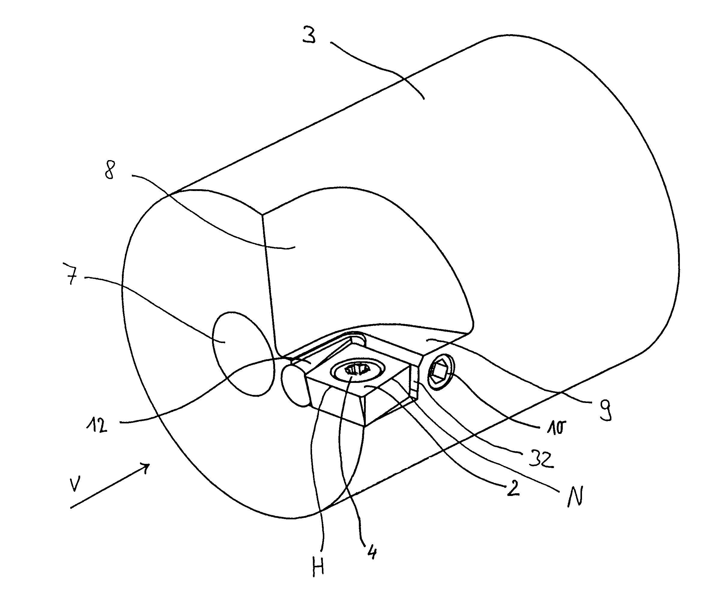
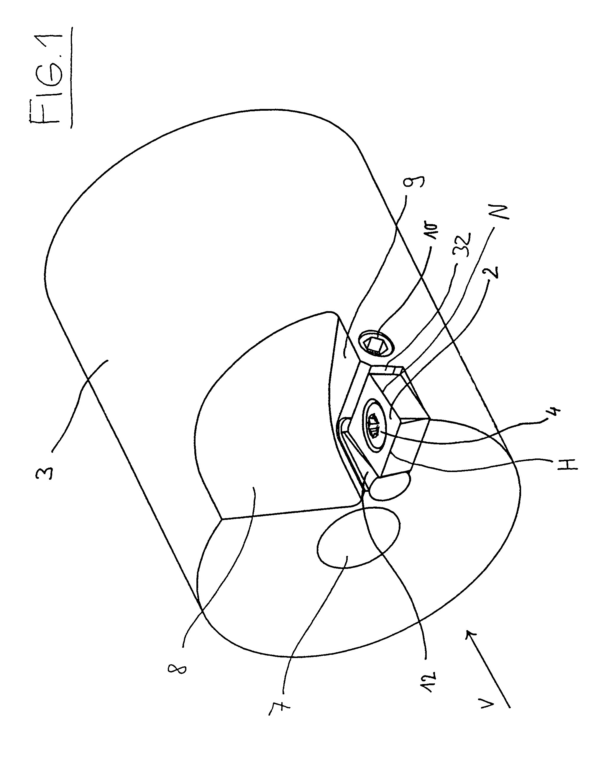
[0074]First, reference is made to the embodiment of the invention shown in FIG. 1. Further details can be taken from FIGS. 2 to 7.

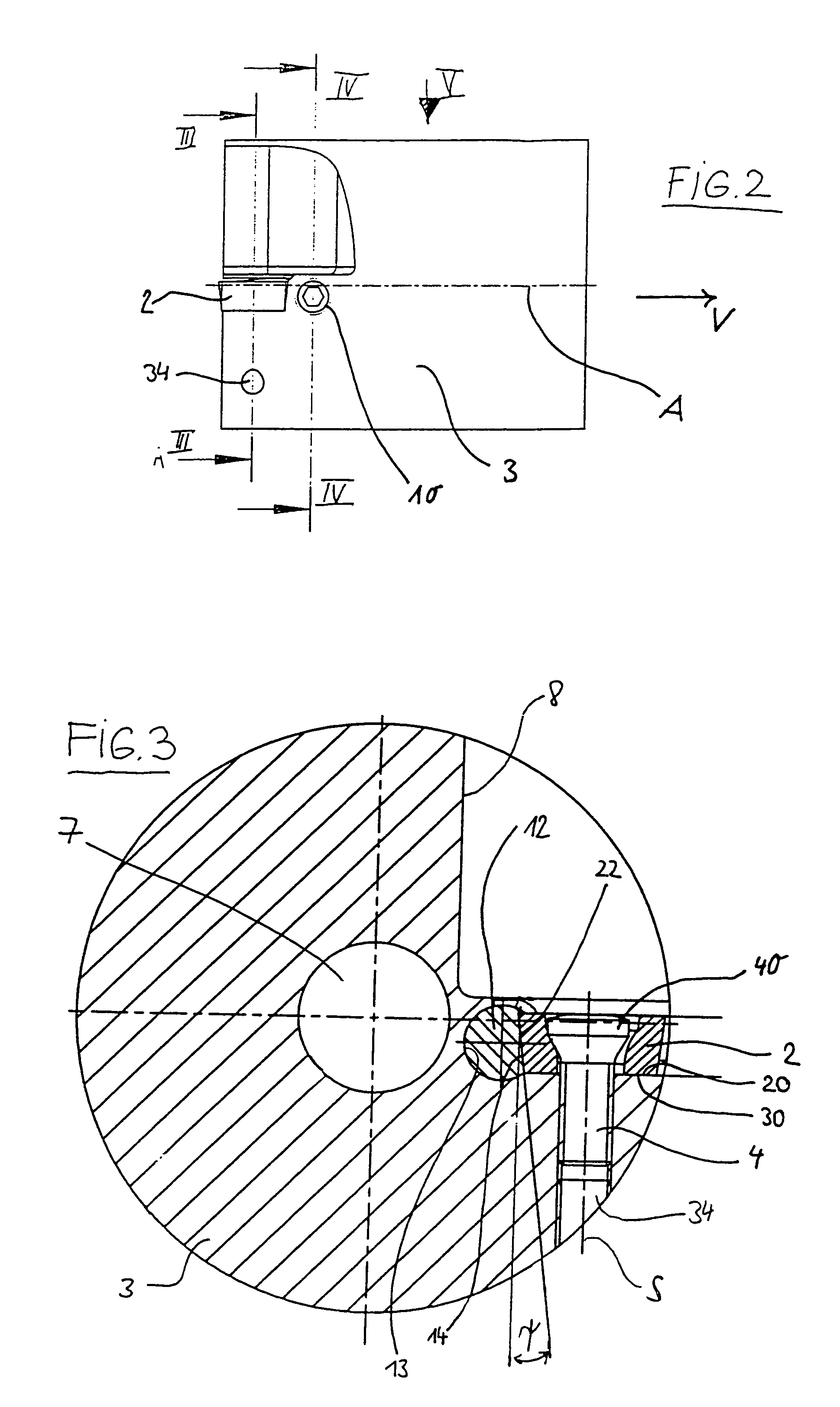
[0075]In FIG. 1, a tool is designated as 1 which has a cutting insert seat on which a cutting insert 2 is screwed down with a tension screw 4. The tension screw 4 is screwed in a centric manner through the cutting insert 2. The adjustment wedge 12 can be adjusted by means of a pressure screw 10 in a displacement direction V and is supported on the tool 3. FIG. 2 shows the tool support 3 in a lateral view. The tool support axis is designated as A and the displacement direction o...


PUM

PropertyMeasurementUnit
Fractionaaaaaaaaaa
Angleaaaaaaaaaa
Angleaaaaaaaaaa

Abstract

A clamping and adjustment apparatus for a cutting tool is described in which a plate-shaped cutter insert is prestressable and fastenable by means of a tension screw with its bottom surface against a seat surface such that it is supported with lateral wall sections in a positionally fixed manner on a cutter support. In order to allow precise adjustment of the cutter insert when little space is available, the clamping and adjustment apparatus has an adjustment wedge which can be actuated by means of a pressure screw in a direction (V) that extends essentially parallel to the seat surface. The adjustment wedge is accommodated in the cutter support in a form-fitted and displaceable manner. The cutter insert is supported on the adjustment wedge and can be adjusted by means of it. Moreover, a tool which is equipped with this clamping and adjustment apparatus is described as well as a tool cartridge which is used for it.

Description

BACKGROUND OF THE INVENTION[0001]1. Field of the Invention[0002]The invention concerns a clamping and adjustment apparatus for a cutting tool, as well as a corresponding cutting tool and a tool cartridge for a cutting tool.[0003]2. Description of Related Art[0004]In generic tools of this sort, the cutters are not located directly on the tool itself but rather on corresponding cutter inserts, particularly exchangeable inserts which are screwed down on the tool. Cutter supports such as cartridges which are fastened to the tool and support corresponding cutting inserts are also known.[0005]Through the use of such cutting inserts, a decoupling of the material of the tool from the material on the cutters occurs which makes it possible to use certain expensive and hard cutting materials such as cermet or the like or coatings such as diamond, whereas the tool shank can be manufactured from a ductile, less expensive material. The important question here concerns a fine setting of the axial ...

Claims


Application Information

Patent Timeline
IPC IPC(8): B23B29/02B23B27/16B23B29/04B23C5/24
CPCB23B27/1681B23B29/046B23C5/2406B23C5/2462Y10T407/1914Y10T407/1928Y10T407/2226Y10T407/1936Y10T407/224B23C2260/84B23C5/24B23C5/2208
Inventor MATHEIS, KLAUS
Owner GUHRING JORG
Why Eureka
Try Eureka