Drainage system and process for operating a regenerative electrochemical cell system

a regenerative fuel cell and electrochemical technology, applied in the field of electrochemical cells, can solve the problems of limited size of water storage vessels employed in regenerative fuel systems, prolonged periods of fuel cell operation,

Inactive Publication Date: 2006-03-21
PROTON ENERGY SYST
View PDF4 Cites 24 Cited by
  • Summary
  • Abstract
  • Description
  • Claims
  • Application Information

AI Technical Summary

Problems solved by technology

During use of the regenerative fuel system, there may be periods where the fuel cell is operated for prolonged periods of time.
Operating in the fuel cell mode for prolonged periods of time may use hydrogen supplied from other than the electrolysis cell and may produce excess by-product water.
Since the size of the water storage vessel employed in regenerative fuel systems is generally limited, excess production of water during fuel cell operation can reach the maximum capacity of the vessel.

Method used


Image

  • Drainage system and process for operating a regenerative electrochemical cell system
  • Drainage system and process for operating a regenerative electrochemical cell system
  • Drainage system and process for operating a regenerative electrochemical cell system

Examples


Embodiment Construction

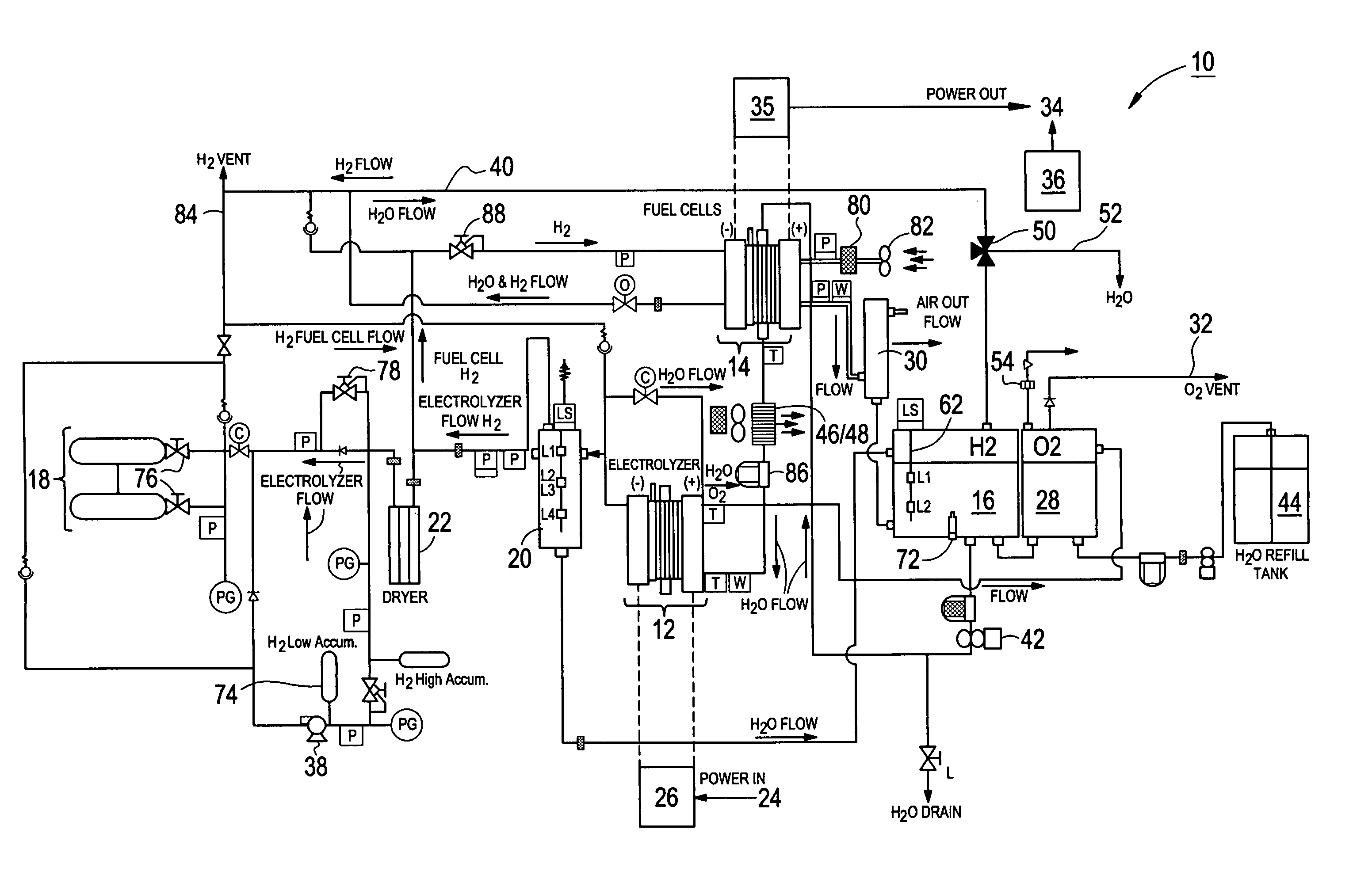
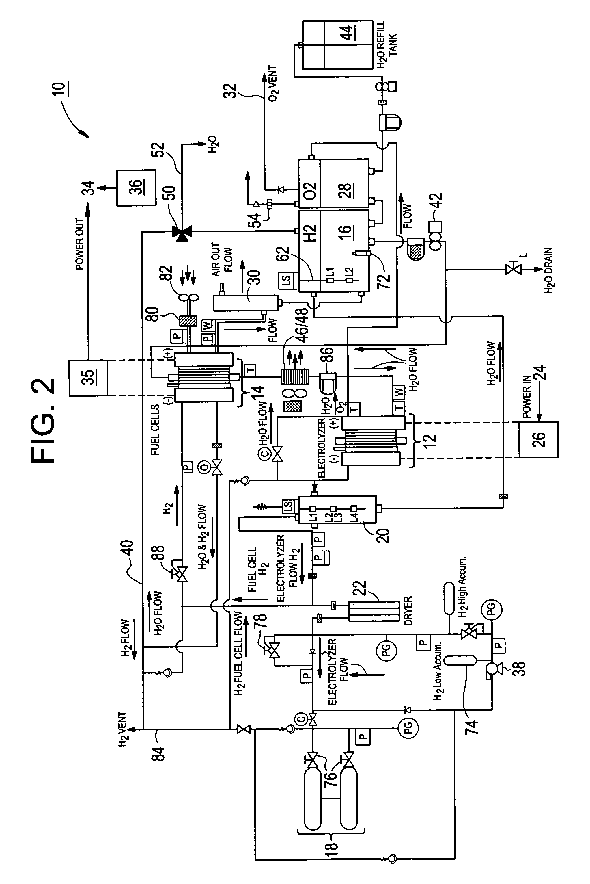
[0016]A regenerative fuel cell system and a process for operating the system are described. The regenerative fuel cell system comprises a drainage system for accommodating excess production of water during prolonged operation of a fuel cell employed in the regenerative fuel system. As used herein, the term “prolonged” is arbitrarily used and depends on numerous factors including, but not limited to, the capacity and number of water storage devices employed in the system, the number of fuel cells employed, hydrogen capacity, configuration of the system, and the like. The drainage system described herein prevents system shut down due to overproduction of water from operation of the fuel cell or otherwise. As will be described in greater detail, in one embodiment, the drainage system is preferably disposed intermediate to the fuel cell outlet and a water storage device adapted to receive water produced by the fuel cell. In another embodiment, the drainage system is disposed at the wate...


PUM

PropertyMeasurementUnit
pressureaaaaaaaaaa
pressuresaaaaaaaaaa
pressuresaaaaaaaaaa

Abstract

An electrochemical cell system comprises: a fuel cell module comprising a fuel cell outlet, an electrolysis module comprising an electrolysis water inlet in fluid communication with a water storage device and a hydrogen gas outlet in fluid communication with a hydrogen storage device, and a drainage system disposed downstream of the fuel cell hydrogen outlet and upstream of the water storage device and configured to remove water from the electrochemical cell system upon water within the water storage device attaining a selected level.

Description

BACKGROUND OF INVENTION[0001]The present disclosure relates to electrochemical cells, and in particular to regenerative fuel cell systems.[0002]Referring to prior art FIG. 1, a partial section of a typical proton exchange membrane fuel cell 100 is detailed. In fuel cell 100, hydrogen gas 112 and reactant water 114 are introduced to a hydrogen electrode (anode) 116, while oxygen gas 118 is introduced to an oxygen electrode (cathode) 120. The hydrogen gas 112 for fuel cell operation can originate from a pure hydrogen source, methanol, or other hydrogen source. Hydrogen gas electrochemically reacts at anode 116 to produce hydrogen ions (protons) and electrons, wherein the electrons flow from anode 116 through an electrically connected external load 121, and the protons migrate through a membrane 122 to cathode 120. At cathode 120, the protons and electrons react with the oxygen gas to form resultant water 114′, which additionally includes any reactant water 114 dragged through membrane...

Claims


Application Information

Patent Timeline
Patent Type & Authority Patents(United States)
IPC IPC(8): H01M8/04H01M8/06H01M8/18
CPCH01M8/04156H01M8/186C25B1/04C25B15/08Y02E60/528Y02E60/366Y10S204/04Y02E60/36Y02E60/50
Inventor HALTER, DEANNOMIKOS, SPYROS
Owner PROTON ENERGY SYST
Why Eureka
Try Eureka