Electronic ballast having end of lamp life, overheating, and shut down protections, and reignition and multiple striking capabilities

a technology of electronic ballast and lamp life, applied in the field of electronic ballast, can solve the problems of overheating and eventually destruction, damage to electronic ballast and gas discharge lamp, and achieve the effect of accurate sense of overheating conditions

Inactive Publication Date: 2006-03-21
UNIVERSAL LIGHTING TECHNOLOGIES
View PDF27 Cites 23 Cited by
  • Summary
  • Abstract
  • Description
  • Claims
  • Application Information

AI Technical Summary

Benefits of technology

[0013]Accordingly, one object of the present invention is to provide an electronic ballast that includes end of lamp life protection, overheating protection, reignition capabilities, and multiple striking capabilities.
[0014]A second object is to provide a ballast end of lamp life protection circuit that is more efficient and consumes less power than prior art end of lamp life protection circuits.

Problems solved by technology

This is an undesirable condition because the ballast is usually very sensitive to the increased power it has to deliver to the lamp and it will be overheated and eventually destroyed by this increased power.
Similarly, this situation can cause damage to the gas discharge lamp.
Once again, the increasing voltage causes the power drawn by the gas discharge lamp and thus the ballast to increase and this can damage both the electronic ballast and the gas discharge lamp.
An overheating condition typically occurs when consumers improperly install electronic ballasts in areas where they cannot be properly cooled.
As a result, these electronic ballasts overheat and eventually fail, resulting in customer dissatisfaction and increased customer costs.
For example, end of lamp life protection circuits taught by the prior art must be designed to handle very high currents and, as a result, dissipate large amounts of power.
This makes these types of protection circuits fairly inefficient.
In addition, many prior art end of lamp life protection circuits sense DC rectification end of lamp life conditions or excessively high AC end of lamp life conditions, but not both.
Known overheating protection circuits suffer from an inability to accurately sense when an overheating condition has occurred and, consequently, do not provide adequate overheating protection.
Prior art reignition circuits can inadvertently attempt to reignite a lamp load even after a ballast has been shut down by another protection circuit.
In addition to the above-referenced disadvantages of prior art protection circuits, the applicant has also recognized that the prior art does not appear to teach one protection circuit that includes all of the desired protection and capabilities described above in an inexpensive, simple but reliable package.
While prior art electronic ballasts do include end of lamp life protection circuits, overheating protection circuits, reignition circuits, multiple striking circuits, or some combination of these features, many of these prior art ballasts require expensive microprocessors or complicated circuits including a large number of component parts to accomplish each protection feature separately, both of which are very undesirable from the consumer and the manufacturer viewpoint.

Method used


Image

  • Electronic ballast having end of lamp life, overheating, and shut down protections, and reignition and multiple striking capabilities
  • Electronic ballast having end of lamp life, overheating, and shut down protections, and reignition and multiple striking capabilities
  • Electronic ballast having end of lamp life, overheating, and shut down protections, and reignition and multiple striking capabilities

Examples


Embodiment Construction

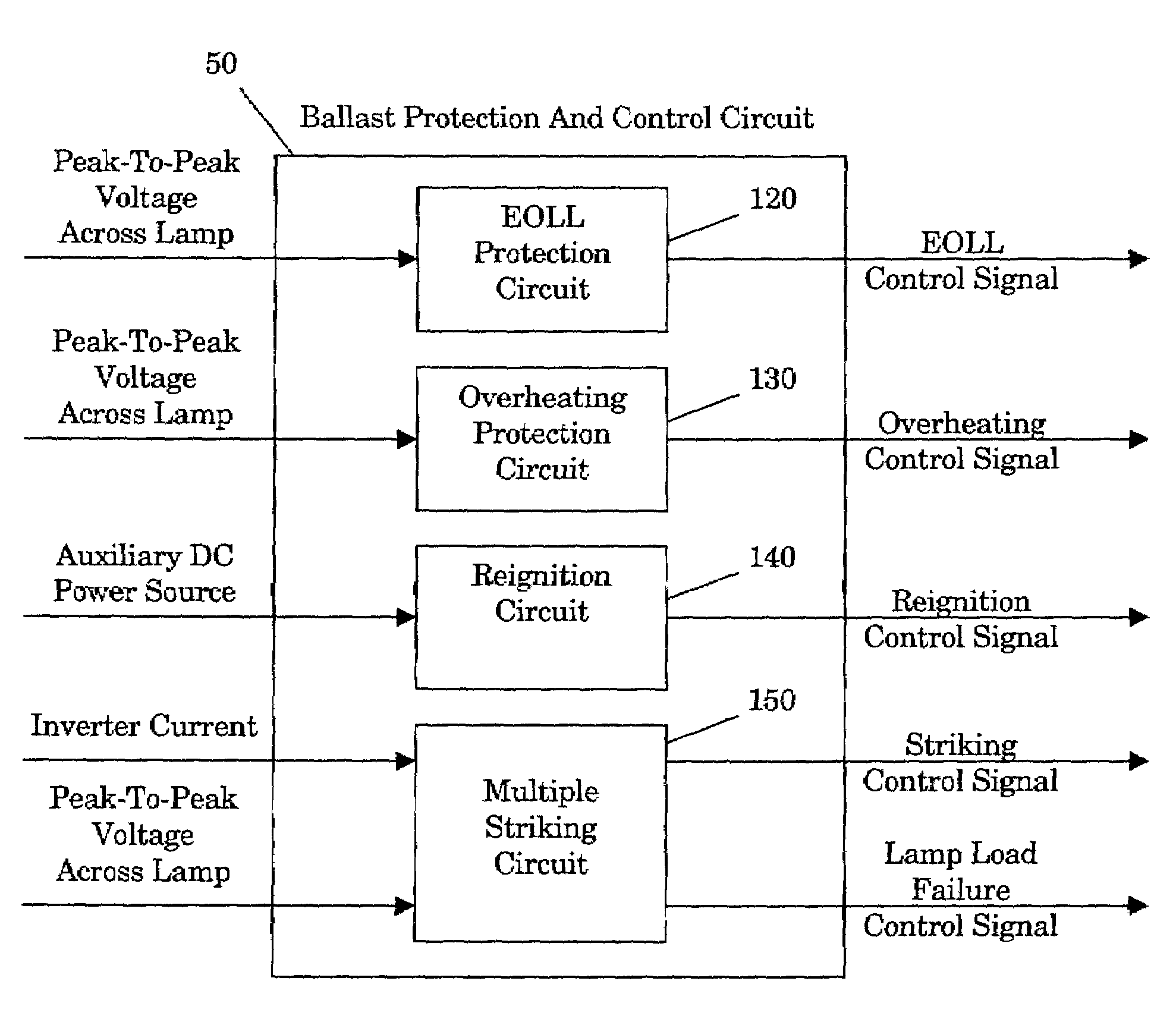
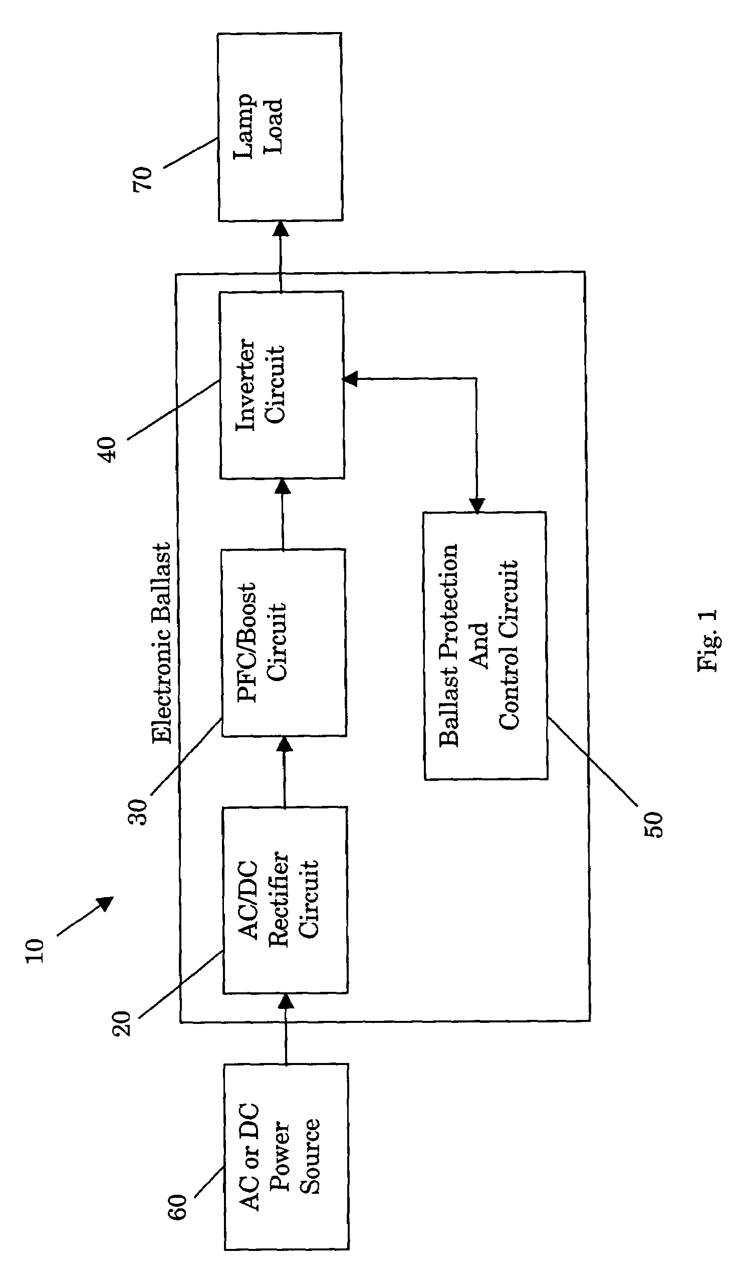
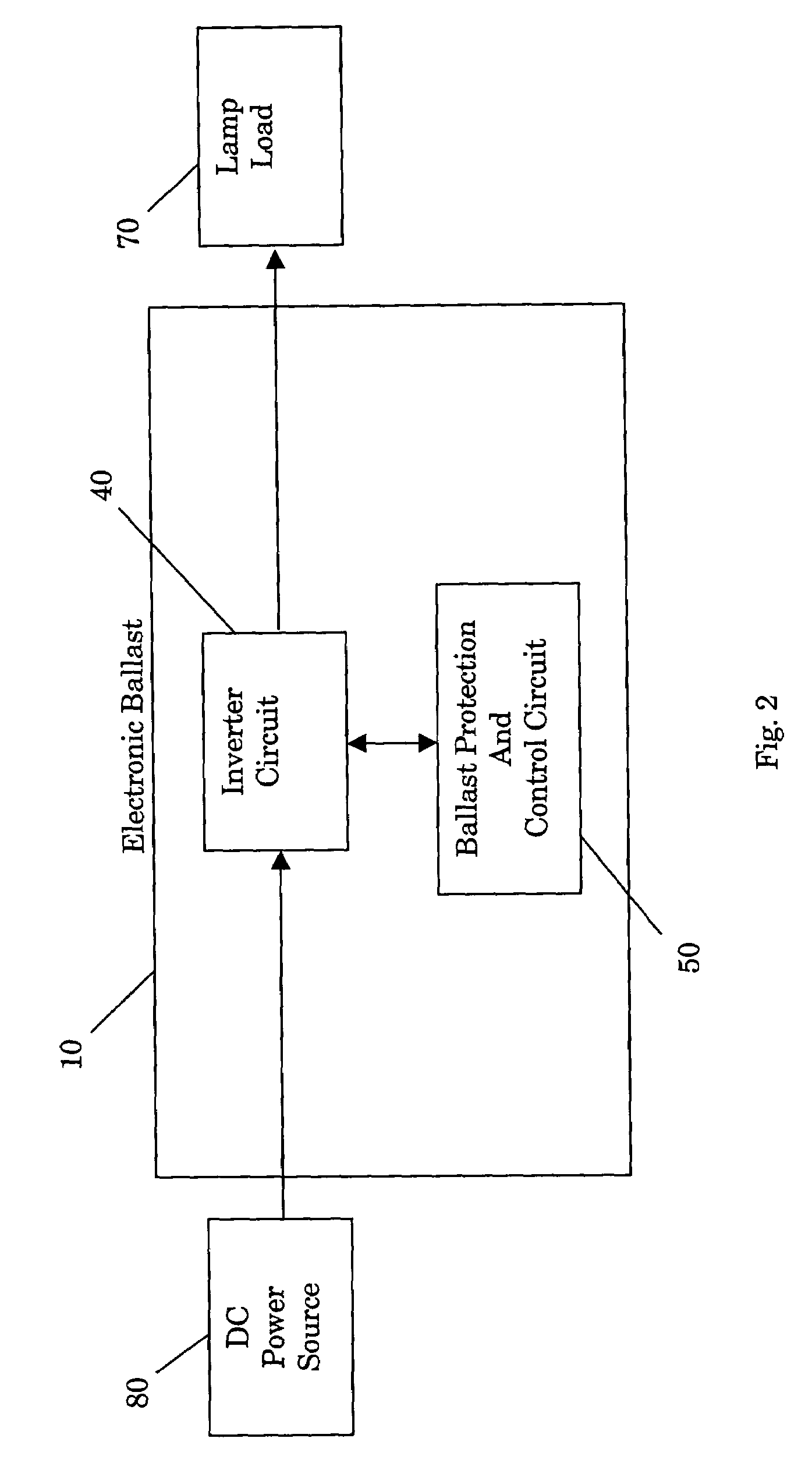
[0036]Referring to FIG. 1, one embodiment of the electronic ballast 10 of the present invention includes an AC / DC rectifier circuit 20 (the rectifier circuit 20), a power factor correction and boost circuit 30 (the PFC / boost circuit 30), an inverter circuit 40 having an associated output resonant circuit 100 (not shown in FIG. 1, but see FIG. 8), and a ballast protection and control circuit 50. The ballast 10 is operable to receive power from an AC or DC power source 60 and to supply power to a gas discharge lamp load 70.

[0037]The AC power source 60 is operable to supply AC voltage and current signals to the lamp load 70 through the electronic ballast 10. Any one of a variety of AC power sources known in the art may be used with the present invention. In a preferred embodiment, the AC power source 60 is simply a local electric utility company AC power source and is accessed using a common electrical outlet found in a typical home or business.

[0038]The AC / DC rectifier circuit 20 (see...


PUM


Abstract

An electronic ballast having end of lamp life and overheating protection, and automatic reignition and multiple striking capabilities includes AC / DC rectifier, PFC / boost, inverter, and ballast protection and control circuits. The ballast protection and control circuit is operable to place the ballast in a protected state when the lamp load connected to the ballast reaches an end of lamp life condition or the ballast overheats. The ballast protection and control circuit also automatically ignites the lamp load when it is connected to the ballast and generates multiple striking attempts for hard to strike lamp loads. The ballast may be connected to AC or DC power sources and different types of lamp loads, and may include various different types of inverter circuits.

Description

[0001]A portion of the disclosure of this patent document contains material that is subject to copyright protection. The copyright owner has no objection to the facsimile reproduction by anyone of the patent document or the patent disclosure, as it appears in the Patent and Trademark office patent file or records, but otherwise reserves all copyright rights whatsoever.[0002]Be it known that I, Ruhe Shi, a citizen of China, residing at 150 Liberty Drive, Madision, Ala. 35758, have invented a new and useful “Electronic Ballast Having End Of Lamp Life, Overheating, and Shut Down Protections, And Reignition And Multiple Striking Capabilities.”BACKGROUND OF THE INVENTION[0003]The present invention relates generally to electronic ballasts for gas discharge lamps.[0004]More particularly, this invention pertains to an electronic ballast that includes end of lamp life protection, overheating protection, automatic shut-down protection capabilities, reignition capabilities, and multiple striki...

Claims


Application Information

Patent Timeline
Patent Type & Authority Patents(United States)
IPC IPC(8): H05B37/00H05B41/285
CPCH05B41/2856H05B41/2855
Inventor SHI, RUHE
Owner UNIVERSAL LIGHTING TECHNOLOGIES
Why Eureka
Try Eureka