Active Q-point stabilization for linear interferometric sensors

a technology of interferometric sensors and q-point stabilization, applied in the field of optical sensors, can solve the problems of complex processing systems for interferometric sensors, which must count these fringes, and the processing system of intensity-based sensors is typically more complex and therefore more expensiv

Inactive Publication Date: 2006-03-21
PRIME PHOTONICS LC
View PDF3 Cites 33 Cited by
  • Summary
  • Abstract
  • Description
  • Claims
  • Application Information

AI Technical Summary

Problems solved by technology

Intensity-based sensors are typically processed by detecting an intensity of light transmitted by, or attenuated by, the sensor as a function of a fluctuating measurand (e.g., pressure, temperature, etc.) The systems for processing the output of such sensors are relatively uncomplicated; however, they are sensitive to signal fading due to perturbations in operating parameters other than the measurand.
The processing systems for interferometric sensors, which must count these fringes, are typically more complex, and therefore more costly, than the processing systems for intensity-based sensors.
These systems are also subject to fringe direction ambiguity (i.e., a change in direction of the measurand at a peak or trough of a fringe may not be detected).
However, interferometric sensor systems involving fringe counting are not as sensitive to non-measurand operating parameter drifts as intensity-based sensors.
The SCIIB sensor configuration involves splitting a return from a sensor into which broadband light has been input into two channels: an unfiltered reference signal in which no interference is observed, and a signal channel which is optically filtered to narrow the spectrum such that coherence length of the light in the signal channel exceeds the difference in length of the optical paths of the reflections in the sensor, which results in interference.
Unfortunately, maintaining the Q-Point in the optimal location is difficult.
Assembling the sensor to fix the Q-Point in the optimal location requires assembly tolerances on the order of tens of nanometers, which is very difficult.
In addition, changes in the physical dimensions of the sensor due to thermal expansion or contraction resulting from temperature changes will cause a drift in the Q-Point from the optimal location.

Method used


Image

  • Active Q-point stabilization for linear interferometric sensors
  • Active Q-point stabilization for linear interferometric sensors
  • Active Q-point stabilization for linear interferometric sensors

Examples


Embodiment Construction

[0019]The present invention will be discussed with reference to preferred embodiments of linear interferometric sensor systems. Specific details are set forth in order to provide a thorough understanding of the present invention. The preferred embodiments discussed herein should not be understood to limit the invention. Furthermore, for ease of understanding, certain method steps are delineated as separate steps; however, these steps should not be construed as necessarily distinct nor order dependent in their performance.

[0020]The present invention is believed to be particularly useful in the context of a SCIIB sensor system and hence will be discussed primarily in that context herein. The invention should not be understood to be limited to a SCIIB sensor system but rather should be understood to be applicable to a wide variety of interferometric sensor systems.

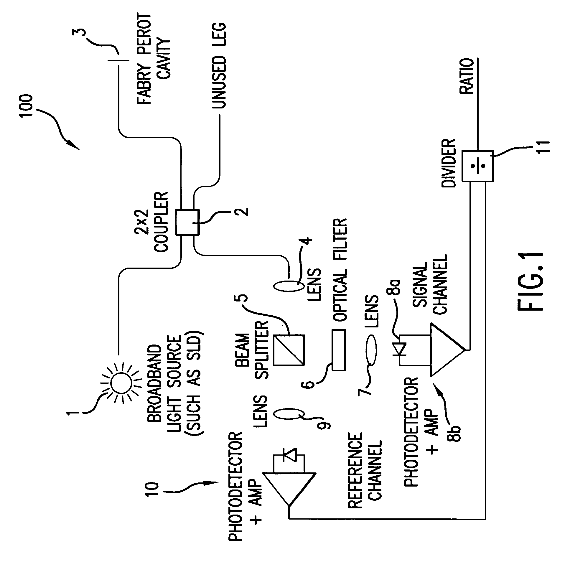
[0021]A conventional SCIIB sensor configuration 100 is illustrated in FIG. 1. In the SCIIB sensor configuration 100, light ...


PUM


Abstract

A linear interferometric sensor system in which the light output from the interferometric sensor is optically bandpass filtered before conversion to an electrical signal by an adjustable band-pass filtering device and the center wavelength of the adjustable band-pass filtering device is controlled by a feedback circuit responsive to the steady state component of the electrical signal corresponding to the filtered sensor return. In a preferred embodiment, the adjustable band-pass filtering device is an electrically tunable optical filter. The invention is particularly useful in self calibrating interferometric / intensity-based sensor configuration, but can be used with other linear interferometric sensor configurations.

Description

[0001]This application claims priority from U.S. Provisional Application Ser. No. 60 / 413,468 filed Sep. 26, 2002. The entirety of that provisional application is incorporated herein by reference.BACKGROUND OF THE INVENTION[0002]1. Field of the Invention[0003]The invention relates to optical sensors generally, and more particularly to linear interferometric optic sensors.[0004]2. Discussion of the Background[0005]Several types of optical sensors (fiber optic or otherwise) are known, including intensity based and interferometric sensors. Intensity-based sensors are typically processed by detecting an intensity of light transmitted by, or attenuated by, the sensor as a function of a fluctuating measurand (e.g., pressure, temperature, etc.) The systems for processing the output of such sensors are relatively uncomplicated; however, they are sensitive to signal fading due to perturbations in operating parameters other than the measurand. Examples of intensity-based sensors include the pr...

Claims


Application Information

Patent Timeline
Patent Type & Authority Patents(United States)
IPC IPC(8): G01B9/02G01D5/353
CPCG01D5/35303
Inventor MAY, RUSSELL
Owner PRIME PHOTONICS LC
Why Eureka
Try Eureka