Check patentability & draft patents in minutes with Patsnap Eureka AI!

Digital signal modulation method, digital signal modulation apparatus, encoding method, encoding apparatus, storage medium, transmission apparatus and program

a digital signal and modulation method technology, applied in the field of digital signal modulation methods, digital signal modulation apparatuses, encoding methods, encoding apparatuses, transmission apparatus and programs, can solve the problem of inability to use direct-current components, and achieve the effect of better suppression of direct-current component characteristics

Inactive Publication Date: 2006-03-21
JVC KENWOOD CORP A CORP OF JAPAN
View PDF14 Cites 6 Cited by
  • Summary
  • Abstract
  • Description
  • Claims
  • Application Information

AI Technical Summary

Benefits of technology

[0019]In view of he above-described drawbacks, it is an object of the present invention to provide a digital signal modulation method which performs run-length limited encoding targeting at a discoid high-density storage medium such as optical disk by using encode tables which convert data consisting of p bits into a code word consisting of q bits, enables a DSV control method having a better direct-current component suppression characteristic than that in the prior art and can inexpensively provide a structure of a modulation apparatus adopting the DSV control method, a digital signal modulation apparatus, a storage medium, a transmission apparatus, and a program.
[0021]It is still another object of the present invention to provide an encoding method which can demonstrate the higher DC suppression capability as compared with the prior art in the same degree of redundancy, an encoding apparatus, a storage medium and a program.

Problems solved by technology

In this mode, however, a direct-current component is generated when digital-modulating a digital information signal in which 0 or 1 longly continues, and this direct-current component can not be used in, for example, magnetic recording which can not reproduce a direct-current signal.

Method used


Image

  • Digital signal modulation method, digital signal modulation apparatus, encoding method, encoding apparatus, storage medium, transmission apparatus and program
  • Digital signal modulation method, digital signal modulation apparatus, encoding method, encoding apparatus, storage medium, transmission apparatus and program
  • Digital signal modulation method, digital signal modulation apparatus, encoding method, encoding apparatus, storage medium, transmission apparatus and program

Examples


second embodiment

[0160]A second embodiment according to the present invention will now be described with reference to the drawings. In FIG. 10, like reference numerals denote parts equal to those in FIG. 1. FIG. 10 is a schematic structural view showing an example of the digital signal recording apparatus adopting the digital signal modulation method and the digital signal modulation apparatus according to the present invention. In the drawing, the digital signal recording apparatus 1R consists of the digital signal modulator 10 and the recording drive portion 15. The digital signal modulator 10 constituted by the formatting portion 11, the p-q modulation portion 22, the coding tables 231, 232, . . . , 23n and the NRZI (Non Return to Zero Inverse) conversion portion 14. The digital signal recording apparatus 1R modulates an inputted digital information signal by the digital signal modulator 10 and obtains a digital modulation signal. Thereafter, the digital signal recording apparatus 1R performs hig...

fourth embodiment

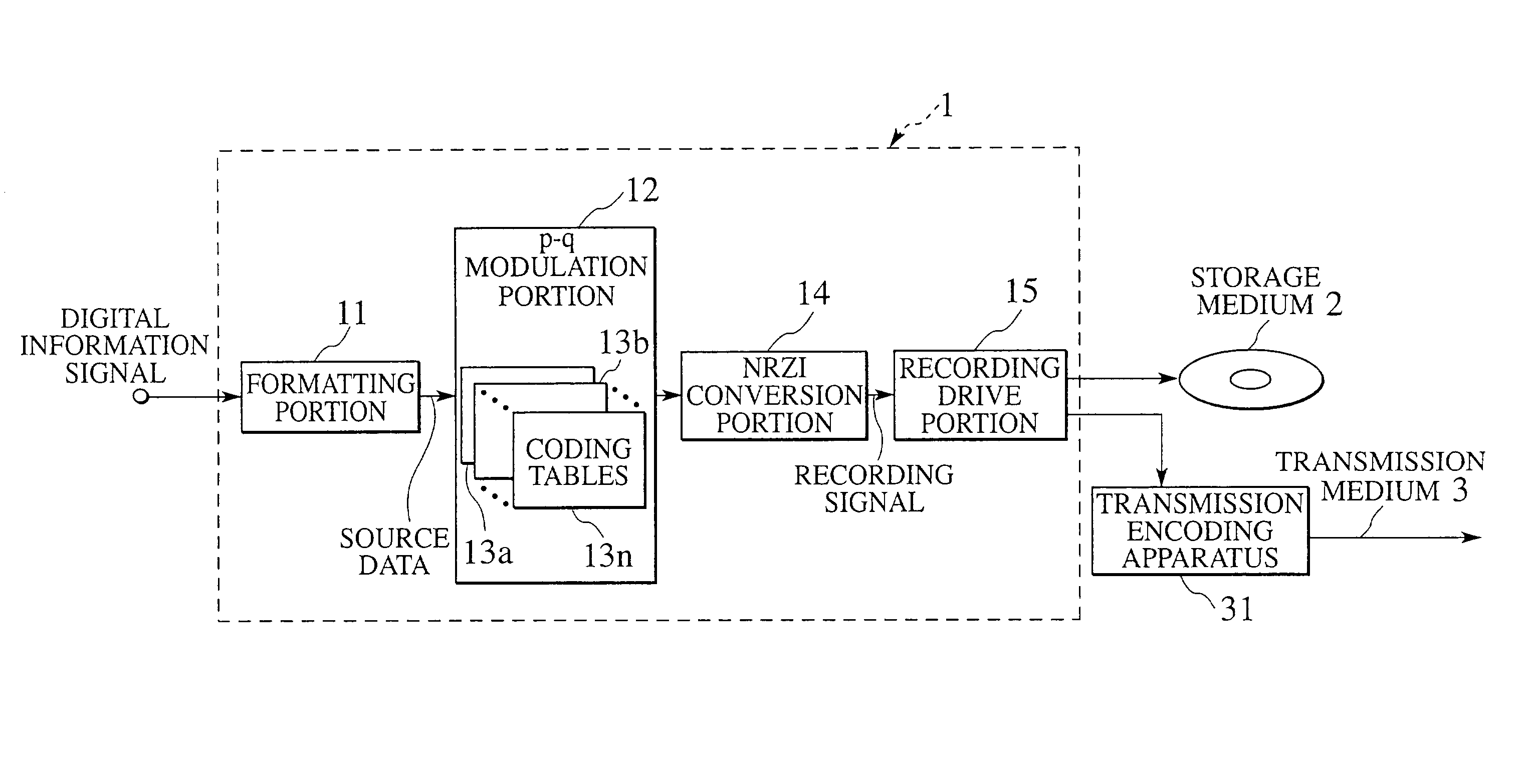
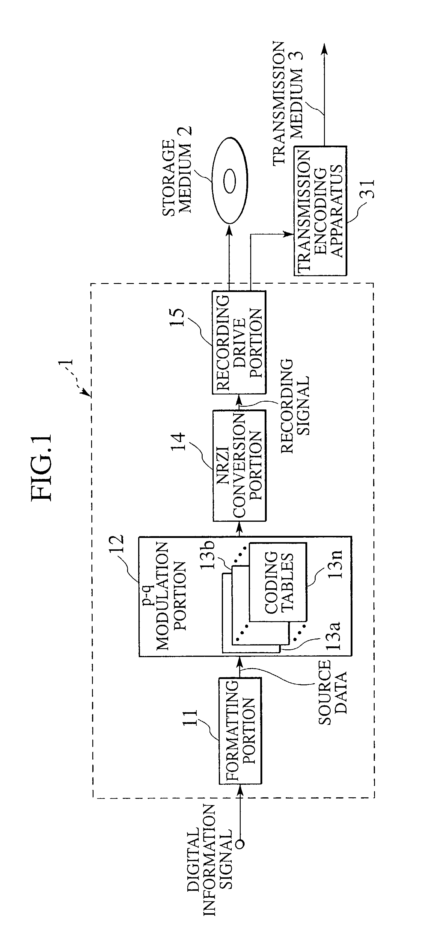
[0242]A fourth embodiment according to the present invention will now be described with reference to the drawings. FIG. 21 is a block diagram showing an encoding apparatus according to the present invention, and FIG. 22 is a block diagram of the fourth embodiment showing a primary part of the encoding apparatus according to the present invention. An encoding apparatus 1E according to an embodiment of the present invention will first be described with reference to FIG. 21. A digital information signal obtained by converting an image or sound which should be encoded into a binary sequence by using non-illustrated dispersing means is subjected to so-called formatting such as addition of an error correction code or sector structuralization in accordance with a recording format of a storage medium 2 in a formatting portion 11, turned into source code series each consisting of four bits, and thereafter added to a 4–6 modulation portion 32.

[0243]The 4–6 modulation portion 32 performs encod...


PUM


Abstract

First and second synchronous words having respective numbers of times of inversion different from each other in NRZI conversion are generated in a synchronous word generation portion, and first and second code word series data are generated by arranging code word data generated making reference to a run-length coding table after these two synchronous words. With respect to the first and second code word series data, DSV calculation results stored in two DSV calculation peak value memories corresponding to these data are compared with each other by a peak value comparison portion. Based on a comparison result, the code word series data having a smaller direct-current component generated in NRZI conversion is selected.

Description

BACKGROUND OF THE INVENTION[0001]1. Field of the Invention[0002]The present invention relates to a digital signal modulation method capable of accurately performing lower component suppression control for suppressing a lower component in a recording code series when converting data of a digital information signal consisting of p (p is a positive integer) bits into a code word consisting of q (q is an integer larger than p) bits and recording it on a high-density storage medium such as an optical disk, a magnetic disk and a magnetic tape by using a code series satisfying a predetermined run-length limited rule, a digital signal modulation apparatus, a storage medium, a transmission apparatus and a program, and to an encoding method used when recording / reproducing data to / from a storage medium or the like, an encoding apparatus, a storage medium, and a program for realizing the encoding method.[0003]2. Description of the Related Art[0004]As a digital signal modulation mode used for re...

Claims


Application Information

Patent Timeline
IPC IPC(8): G11B5/09G11B20/14H03M5/14
CPCH03M5/145G11B20/1426
Inventor HAYAMI, ATSUSHIOKI, TSUYOSHIKUROIWA, TOSHIO
Owner JVC KENWOOD CORP A CORP OF JAPAN
Features
  • R&D
  • Intellectual Property
  • Life Sciences
  • Materials
  • Tech Scout
  • Unparalleled Data Quality
  • Higher Quality Content
  • 60% Fewer Hallucinations
Learn More