
Emergency call load management for call centers

a call center and call load technology, applied in the field of telecommunications, can solve the problems of public-service call-centers, or the system of such call-centers, center overloaded with callers, etc., and achieve the effect of reducing call overloading

Inactive Publication Date: 2006-03-21
GENESYS TELECOMMUNICATIONS LABORATORIES INC
View PDF7 Cites 9 Cited by
  • Summary
  • Abstract
  • Description
  • Claims
  • Application Information

AI Technical Summary

Benefits of technology

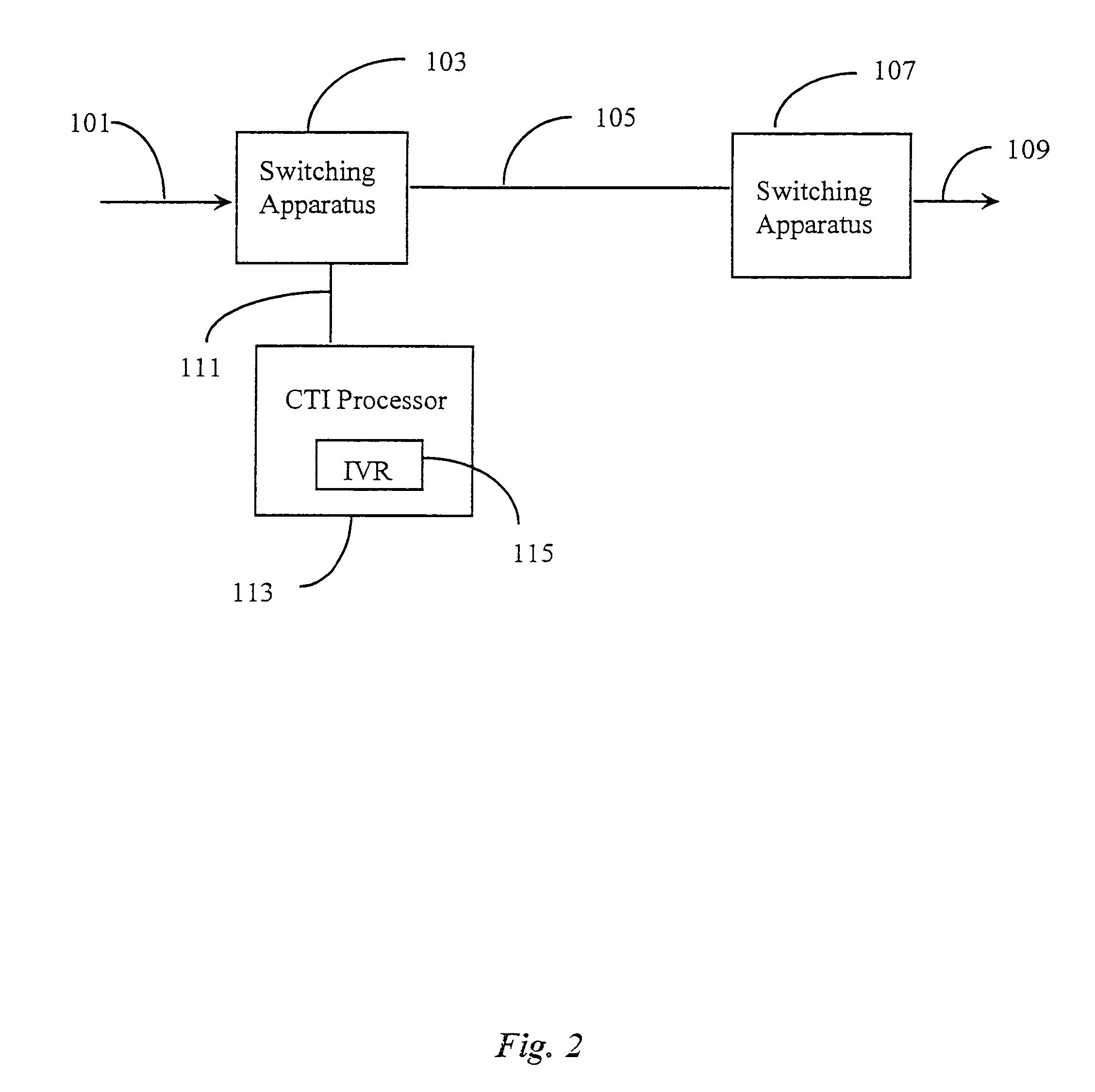
The present invention provides a system for handling call loads in telecommunications networks. The system includes a switching apparatus and an interactive voice-response (IVR) selective routing unit. The IVR unit is connected to the switching apparatus and can handle selected calls. The calls can be diverted to the IVR unit for negotiating with the calling party, and the calls can be processed based on specific rules. The system can also be used in data-network telephony networks, such as the Internet. The technical effect of the invention is to automatically handle and alleviate call overloading in telephony networks, reducing the burden on call centers and ensuring efficient call processing.

Problems solved by technology

Even with present levels of CTI there are still problems in operating public-service call-centers, or a system of such call centers, especially in times of emergency.
Other difficulties accrue, for example, when there are hardware or software degradations, failures, or overloads in one or more parts of a system, perhaps due to natural disaster.
Another problem presents itself when authorized personnel such as rescue workers, police officials, fire officials, and the like attempt to connect to needed services only to find the centers overloaded with callers having needs of lesser importance.
Still other problems accrue due to known latency in conventional equipment contributing to a high call-volume overload during emergency periods.

Method used


Image

  • Emergency call load management for call centers
  • Emergency call load management for call centers
  • Emergency call load management for call centers

Examples


Embodiment Construction

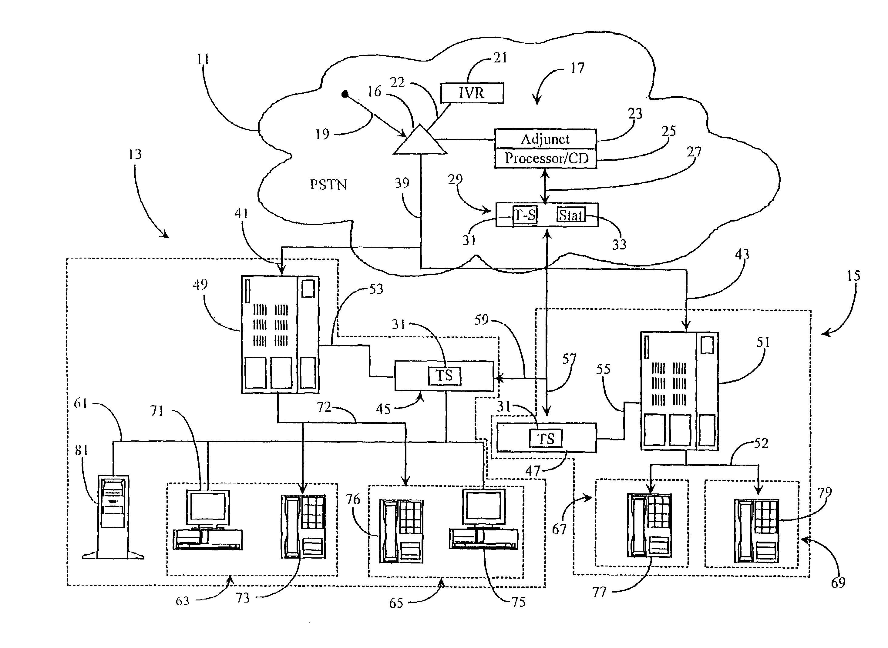
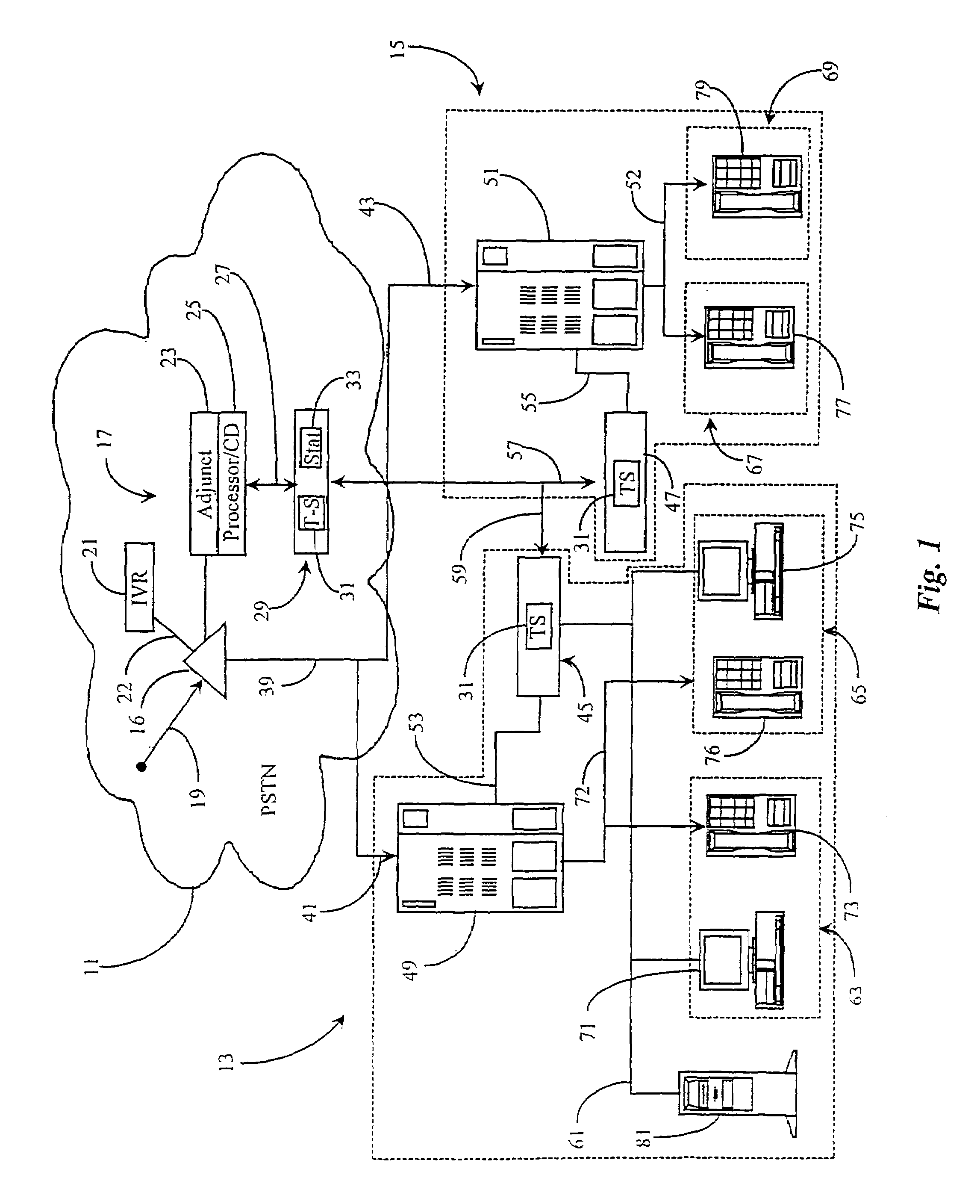
[0024]FIG. 1 is an overview of a system with call-load management capability according to a relatively narrow embodiment of the present invention. In this example, there are two call-centers illustrated, call center 13 and call center 15. Both call centers 13 and 15 are connected to a PSTN network 11 via telephony trunks 41, and 43 respectively. Call-centers 13 and 15, in this particular embodiment, are emergency service-centers as described in the background section, but may in practice be any type of call center to which a heavy load of calls may be directed for any reason.

[0025]Network 11 will typically be a public telephone network as shown, but may also be another type of network as known in the art such as a private telephone network or a data network telephony network like the Internet. In this example a service control point (SCP) 17 is provided within cloud 11 as a reference for routing incoming calls to a switching apparatus 16, calls represented vector 19. Calls 19 may or...


PUM


Abstract

An emergency call load handling system in a call network has an interactive voice response (IVR) unit associated with a switching apparatus to which calls may be diverted in special conditions, such as during emergencies or disasters when calls to certain destinations may suddenly increase dramatically. Calls are diverted depending on call destination and / or pre-programmed triggers, such as a call load threshold experienced by the switching apparatus or for a specific destination. The IVR unit in some cases negotiates with callers for priority to further route calls, and may play pre-recorded messages. Low priority calls are typically disposed of to for fire stations, hospitals, government emergency handling centers and the like. In some cases rules may be amended in real time by use of data network connections between call centers and the SCPs involved.

Description

[0001]The present application is a continuation application of patent application Ser. No. 09 / 438,675 entitled “Emergency Call Load Management for Call Centers,” filed on Nov. 12, 1999, now U.S. Pat. No. 6,788,781 which is a divisional of Ser. No. 09 / 128,273 filed Aug. 3, 1998 now abandoned, which are incorporated in their entirety by reference.FIELD OF THE INVENTION[0002]The present invention is in the field of telecommunications and has particular application to methods and apparatus for managing call loading to call centers under disaster or other emergency conditions.BACKGROUND OF THE INVENTION[0003]Telephone call processing and switching systems are, at the time of the present patent application, relatively sophisticated, computerized systems, and development and introduction of new systems continues. Much information on the nature of such hardware and software is available in a number of publications accessible to the present inventors and to those with skill in the art in gen...

Claims


Application Information

Patent Timeline
Patent Type & Authority Patents(United States)
IPC IPC(8): H04M3/00G06Q40/00H04M3/523
CPCG06Q40/04H04M3/523
Inventor SHTIVELMAN, YURI
Owner GENESYS TELECOMMUNICATIONS LABORATORIES INC
Learn More