
Data transmission over multiple upstream channels within a cable modem system

a data transmission and cable modem technology, applied in the field of upstream transmission of data, can solve the problems of reducing the channel capacity of the cable system, degrading the signal quality, and the cable system did not have the equipment necessary to send signals from subscribers to the head end, so as to increase the bandwidth and increase the reliability of data transmission.

Inactive Publication Date: 2006-03-21
CISCO SYSTEMS INC
View PDF8 Cites 83 Cited by
  • Summary
  • Abstract
  • Description
  • Claims
  • Application Information

AI Technical Summary

Benefits of technology

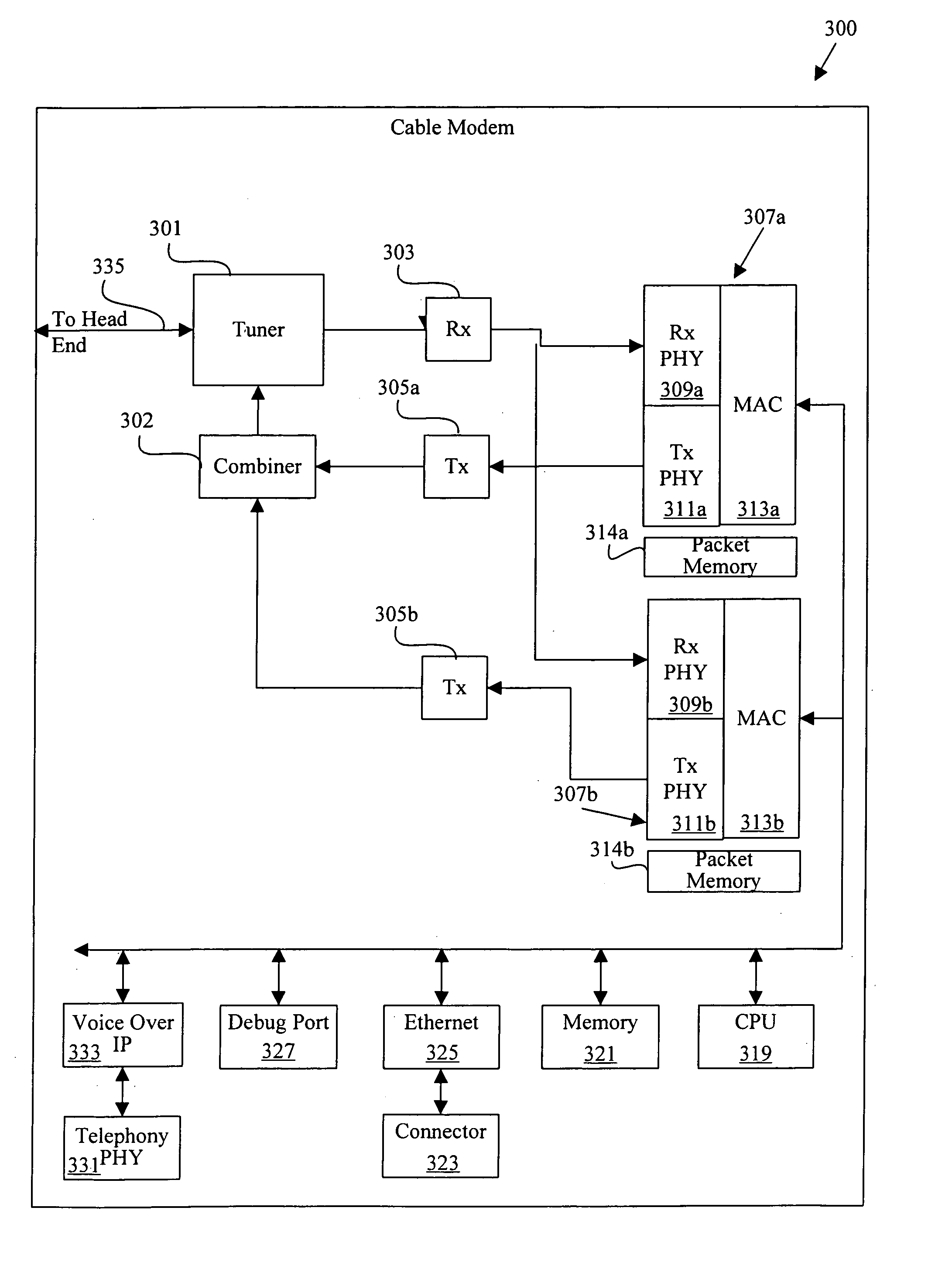
[0029]The present invention has several associated advantages. For example, the present invention provides mechanisms for configuring a cable modem to transmit on two or more channels. This features provides a significant increase in bandwidth over the single upstream channel configuration. Additionally, if one of the multiple upstream channels of a cable modem becomes unable to transmit data, another upstream channel may take over transmission. Thus, the present invention may increase the reliability of data transmission.

Problems solved by technology

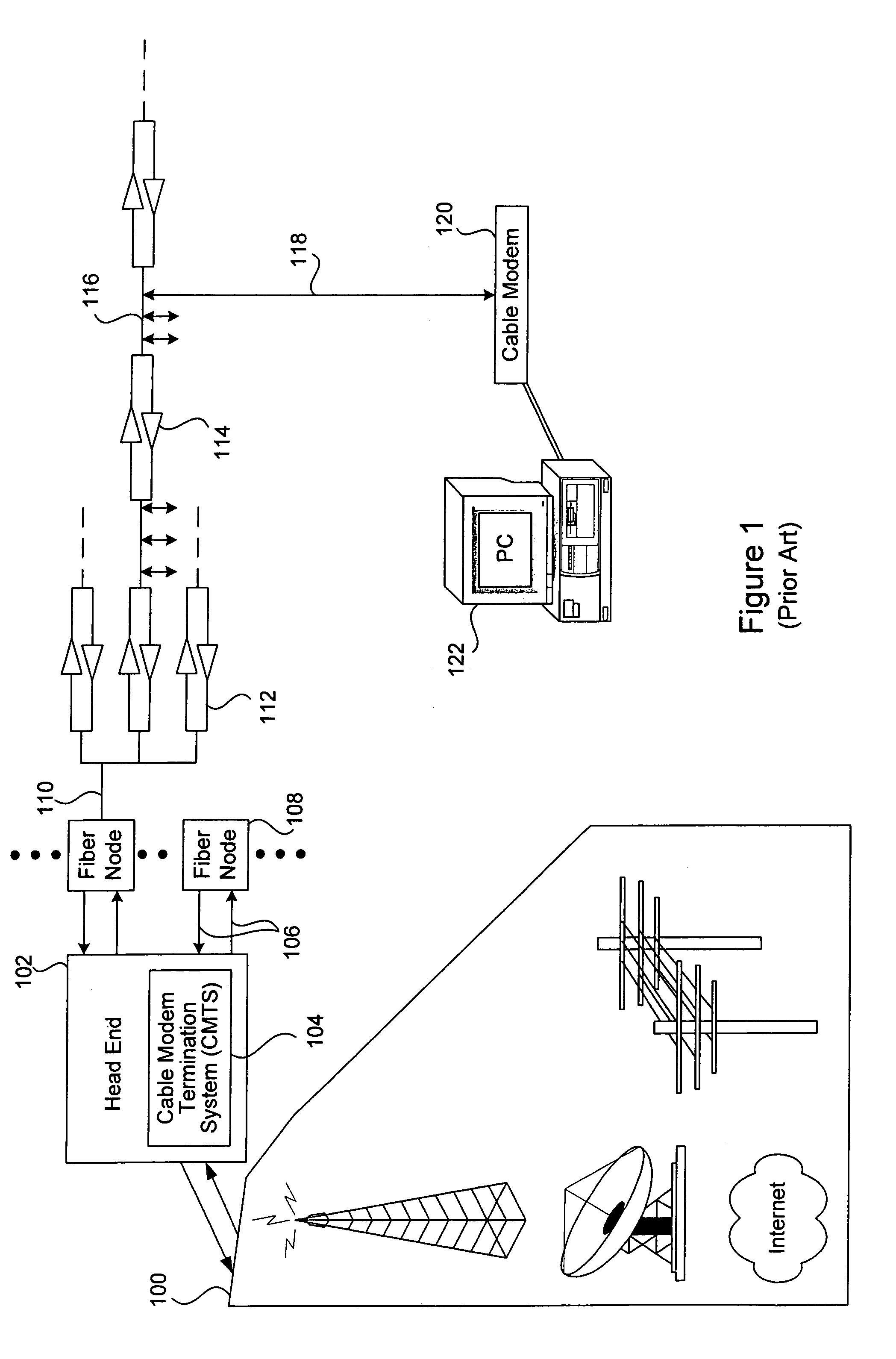
However, the cable system did not have the equipment necessary for sending signals from subscribers to the head end, known as return or upstream signal transmission.
In addition, because cable modems were not used, the head end of pre-HFC cable systems did not contain a CMTS.
Amplifiers decrease a cable system's channel capacity, degrade the signal quality, and are susceptible to high maintenance costs.
Although a 10 Mbps data transmission bandwidth is adequate for transmitting certain types of data that do not require large amounts of bandwidth (e.g., file transfers), a 10 Mbps bandwidth is inadequate for transmitting data that requires a larger amount of bandwidth (e.g., real time voice and video conferencing).

Method used


Image

  • Data transmission over multiple upstream channels within a cable modem system
  • Data transmission over multiple upstream channels within a cable modem system
  • Data transmission over multiple upstream channels within a cable modem system

Examples


Embodiment Construction

[0039]Reference will now be made in detail to specific embodiments of the invention. Examples of these embodiments are illustrated in the accompanying drawings. While the invention will be described in conjunction with these specific embodiments, it will be understood that it is not intended to limit the invention to these embodiments. On the contrary, it is intended to cover alternatives, modifications, and equivalents as may be included within the spirit and scope of the invention as defined by the appended claims. In the following description, numerous specific details are set forth in order to provide a thorough understanding of the present invention. The present invention may be practiced without some or all of these specific details. In other instances, well known process operations have not been described in detail in order not to unnecessarily obscure the present invention.

[0040]The present invention provides mechanisms within a cable modem for transmitting upstream data on ...


PUM


Abstract

A system and method are disclosed for transmitting upstream data from a cable modem within a cable television plant. One aspect of the invention pertains to a method that includes transmitting a first portion of the upstream data on a first upstream channel from the cable modem and transmitting a second portion of the upstream data on a second upstream channel from the cable modem. The second upstream channel differs from the first upstream channel. In another aspect, the invention pertains to a cable modem that includes a processor configured to initiate transmission on multiple upstream channels. The cable modem further includes an upstream transmitting component operating in conjunction with the processor and configurable by the processor to transmit data over multiple upstream channels. In one embodiment, the upstream transmitting component includes a first transmitter that is capable of being configured by the processor to transmit data at both a first upstream channel and a second transmitter that is capable of being configured by the processor to transmit at a second upstream channel that differs from the first upstream channel.

Description

BACKGROUND OF THE INVENTION[0001]1. Field of the Invention[0002]The present invention relates to transmitting data over existing cable television plants using cable modems. More specifically, it relates to upstream transmission of data from the cable modem to the head end.[0003]2. Description of the Related Art[0004]The cable TV industry has been upgrading its signal distribution and transmission infrastructure since the late 1980s. In many cable television markets, the infrastructure and topology of cable systems now include fiber optics as part of its signal transmission component. This has accelerated the pace at which the cable industry has taken advantage of the inherent two-way communication capability of cable systems. The cable industry is now poised to develop reliable and efficient two-way transmission of digital data over its cable lines at speeds orders of magnitude faster than those available through telephone lines, thereby allowing its subscribers to access digital da...

Claims


Application Information

Patent Timeline
IPC IPC(8): H04N7/173
CPCH04N21/6168H04N7/22
Inventor LEE, GLENN E.KING, PATRICK S.
Owner CISCO SYSTEMS INC
Learn More