
Process and apparatus for insulating building roof

Inactive Publication Date: 2006-03-28
CORWIN THOMAS N
View PDF22 Cites 30 Cited by
  • Summary
  • Abstract
  • Description
  • Claims
  • Application Information

AI Technical Summary

Benefits of technology

[0010]In accordance with an aspect of the invention, a building roof supported on rafters is insulated by supporting a rigid insulating panel between the rafters. The rigid insulation panels can be easily installed before installation of a ceiling, and do not have any tendency to bunch up. These features have the advantage that efficient and complete thermal insulation of a building roof can be completed quickly and easily, and before installation of a ceiling.

Problems solved by technology

Because glass fiber insulation batts are pliable and compressible, it can be difficult to install a uniformly thick layer of glass fiber insulation that completely covers the drywall panels forming the ceiling.
Further, it is difficult to provide a uniformly thick space or gap between the insulation and the roof for proper ventilation.
These problems are especially difficult to overcome when wires, electrical boxes or other obstructions are located in the space between the ceiling and the roof.
In the area of such obstructions, the glass fiber insulation batts tend to bunch up.
First, any areas of the ceiling which are not covered with insulation will allow high rates of heat transfer and very substantially negate the potential benefits of the insulation.
Second, bunching up of the insulation can effectively block off ventilation in a portion of the space between the ceiling and the roof, which in turn can result in ice back up under the shingles at the eaves.
A problem with this practice is that any plumbing, electrical, mechanical, ductwork, etc. that is to be installed between the ceiling drywall panels and the roof must be roughed in before the ceiling drywall panels can be installed.
If this preliminary work, which is necessary before installation of the ceiling drywall panels, is not completed before the onset of cold weather then it may become necessary to delay this work until the weather warms up to avoid the difficulties and expenses associated with heating an uninsulated building and / or completing such work in an unheated building.
Further, neither of these patents facilitates installation of thermal roof insulation immediately after the roof rafters have been erected and before the ceiling drywall panels have been installed and before any plumbing, electrical, mechanical, ductwork and other building materials have been roughed in between the drywall and roof.

Method used


Image

  • Process and apparatus for insulating building roof
  • Process and apparatus for insulating building roof
  • Process and apparatus for insulating building roof

Examples


Embodiment Construction

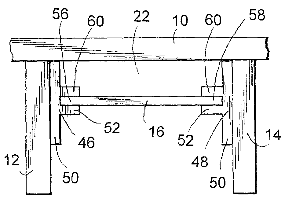
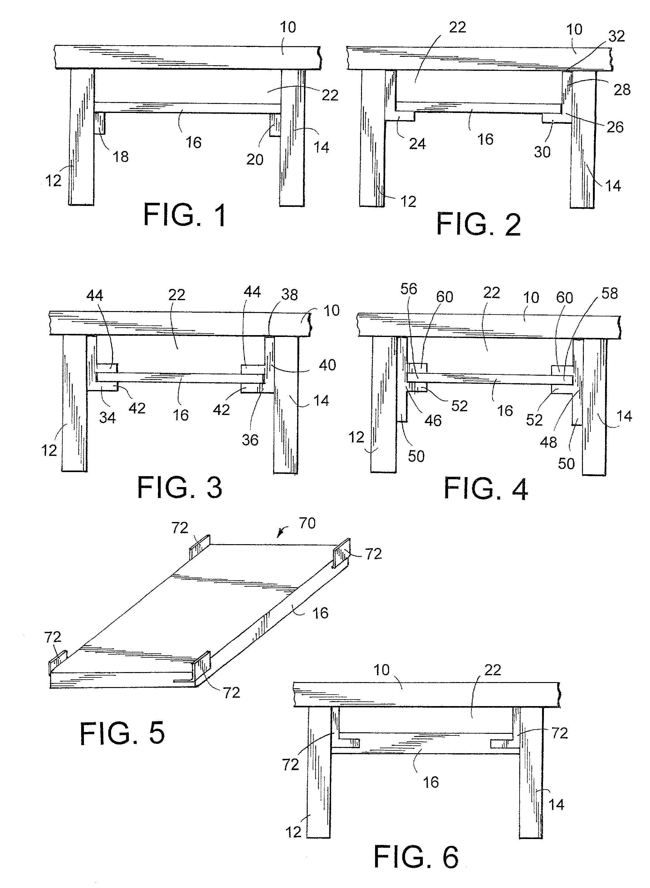
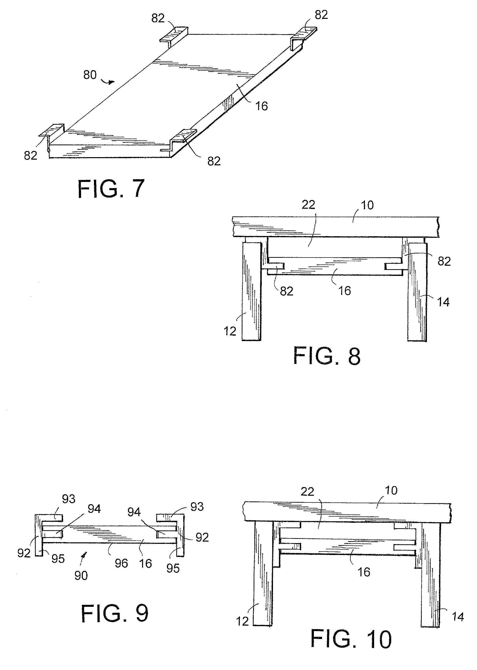
[0023]In FIG. 1, there is shown a building roof 10 supported on rafters 12 and 14. The roof is thermally insulated by supporting a rigid insulation panel 16 below roof 10 and between rafters 12 and 14. An insulation panel 16 can be supported on brackets 18 and 20 fastened to rafters 12 and 14 respectively. Brackets 18 and 20 may be in the form of rails that extend the length of rafters 12 and 14, or brackets 18 and 20 may be relatively short (e.g., one to three inches), with one bracket supporting each of the four corners of a panel 16. Although the process used for insulating a building roof in accordance with the structure shown in FIG. 1 has advantages over the use of alternative methods utilizing glass fiber batt, a disadvantage is that care must be taken to install brackets 18 and 20 on rafters 12 and 14, respectively, at a desired distance from the underside of roof 10 so that insulation panel 16 is spaced from roof 10 to provide an appropriate ventilation gap 22, wherein the ...


PUM


Abstract

An improved process and apparatus for insulating a building roof involves the use of a rigid thermal insulating panel supported between roof rafters. Brackets fastened to the rafters are used to support the rigid thermal insulating panels at a predetermined distance from the roof to provide an appropriate ventilation gap between the roof and the insulation.

Description

FIELD OF THE INVENTION[0001]This invention relates to building insulation and more particularly to processes and apparatus for thermally insulating a roof and / or floor of a building.BACKGROUND OF THE INVENTION[0002]Residential building roofs are typically insulated by laying glass fiber insulation batts onto drywall panels after the drywall panels have been fastened to the roof rafters. Because glass fiber insulation batts are pliable and compressible, it can be difficult to install a uniformly thick layer of glass fiber insulation that completely covers the drywall panels forming the ceiling. Further, it is difficult to provide a uniformly thick space or gap between the insulation and the roof for proper ventilation. These problems are especially difficult to overcome when wires, electrical boxes or other obstructions are located in the space between the ceiling and the roof. In the area of such obstructions, the glass fiber insulation batts tend to bunch up. This has two undesirab...

Claims


Application Information

Patent Timeline
IPC IPC(8): E04B1/74E04B1/76E04D13/16
CPCE04D13/1625E04B1/7654
Inventor CORWIN, THOMAS N.
Owner CORWIN THOMAS N
Learn More