Blind cut down machine

a blind cutting machine and blind cutting technology, applied in the field of blind cutting machines, can solve the problems of not being completely suitable for cutting blinds, shears or cutting blades are not suitable for cutting blind slats, and the metal used in head rails is relatively difficult to cu

Inactive Publication Date: 2006-03-28
SHADE O MATIC
View PDF105 Cites 28 Cited by
  • Summary
  • Abstract
  • Description
  • Claims
  • Application Information

AI Technical Summary

Benefits of technology

[0039]In a simplified form of the invention, both the head rail, and the blind slats, and even the bottom rail, can all be cut by a single slat cutter for example a saw blade, and they can all be held in a single clamp opening. This will become possible where, for example, the head rail and bottom rail are made out of a non-metallic material, such as thermoplastic which is easily cut by means of a saw blade.

Problems solved by technology

However, in general terms, these machines have not been totally suitable for cutting down blinds in which the slats are made of heavier (or thicker) materials, such as wood or thick thermoplastic.
Vertical blinds, as well as horizontal blinds, also use blind slats which are made of heavier or thicker materials such as wood or thick thermoplastic, and earlier machines such as those using shears or cutting blades are not suitable for cutting blind slats either vertical or horizontal, made of these thicker materials.
Clearly, metal such as steel, used in head rails, is relatively hard to cut.
On the other hand, since the sections used in this type of product are relatively thin, the die for cutting the metal components of the blind may only be required to move a short distance.
On the other hand, the cutting of the blind slats themselves presents entirely different problems.
The thickness of all of the blind slats of these heavier materials when bundled together for cutting is considerable.
Consequently, the saw for cutting these heavier, thicker blind slats must move a considerable distance.
While it is relatively easy to provide for the manual operation of such a saw moving a considerable distance for cutting easier to cut thicker materials, the problem becomes more complex when it is understood that it is desirable, at least in the case of horizontal blinds, to cut all of the materials, both the metal head rail and the softer blind slats, in what is essentially a single cutting stroke.
It is not feasible to provide two machines, i.e. a first machine which cuts only the head rail which is usually made of steel, and a second machine for an entirely separate cut for cutting the softer, thicker blind slats.
The moving of the blind from one machine to another will almost inevitably result in some discrepancy between the amount cut off from the head rail and the amount cut off from the blind slats, and the end result will not be satisfactory.
In addition to these problems when cutting down of blind components such as these formed on thermoplastic it is found that thermoplastic material is generally unsuitable for cutting by means of a movable cutting die such as is used for cutting metal sections.
For these reasons therefore the provision of a cutdown machine meeting all of these objectives, i.e. being capable of cutting through both the softer but thicker blind slats, and the harder but thinner metal head rail and bottom rail, and also the softer but thicker thermoplastic head rails and bottom rails of still further blinds, in a single manual cutting movement, and being capable of cutting thicker materials, presents a complex problem.
The complexity of the design is further aggravated by the fact that (in the case of horizontal blinds) the head rail is located at the head of the blind and is usually made of metal, eg. steel, and the blind slats (of thicker material) are located spaced below the head rail.

Method used


Image

  • Blind cut down machine
  • Blind cut down machine
  • Blind cut down machine

Examples


Embodiment Construction

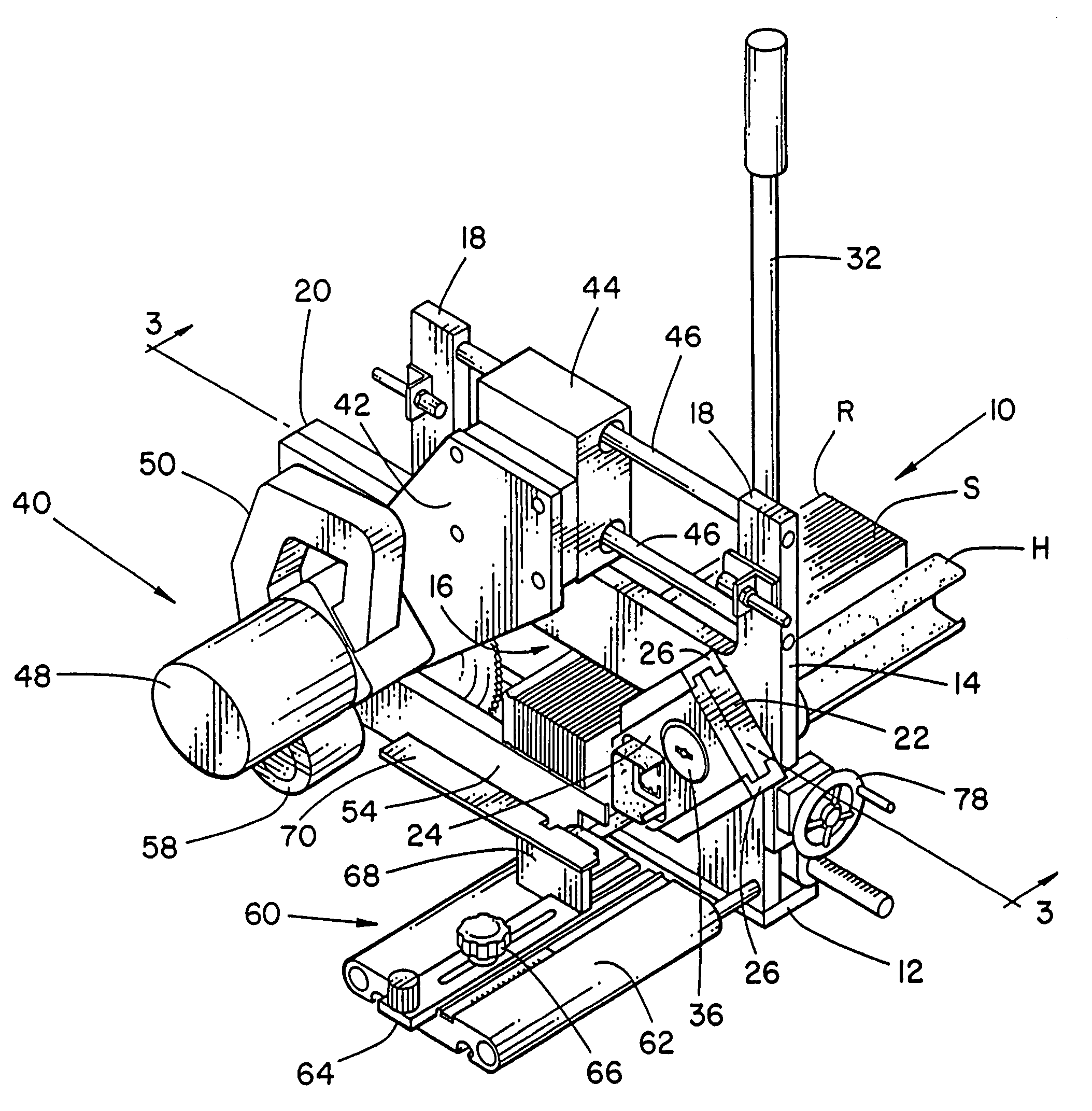
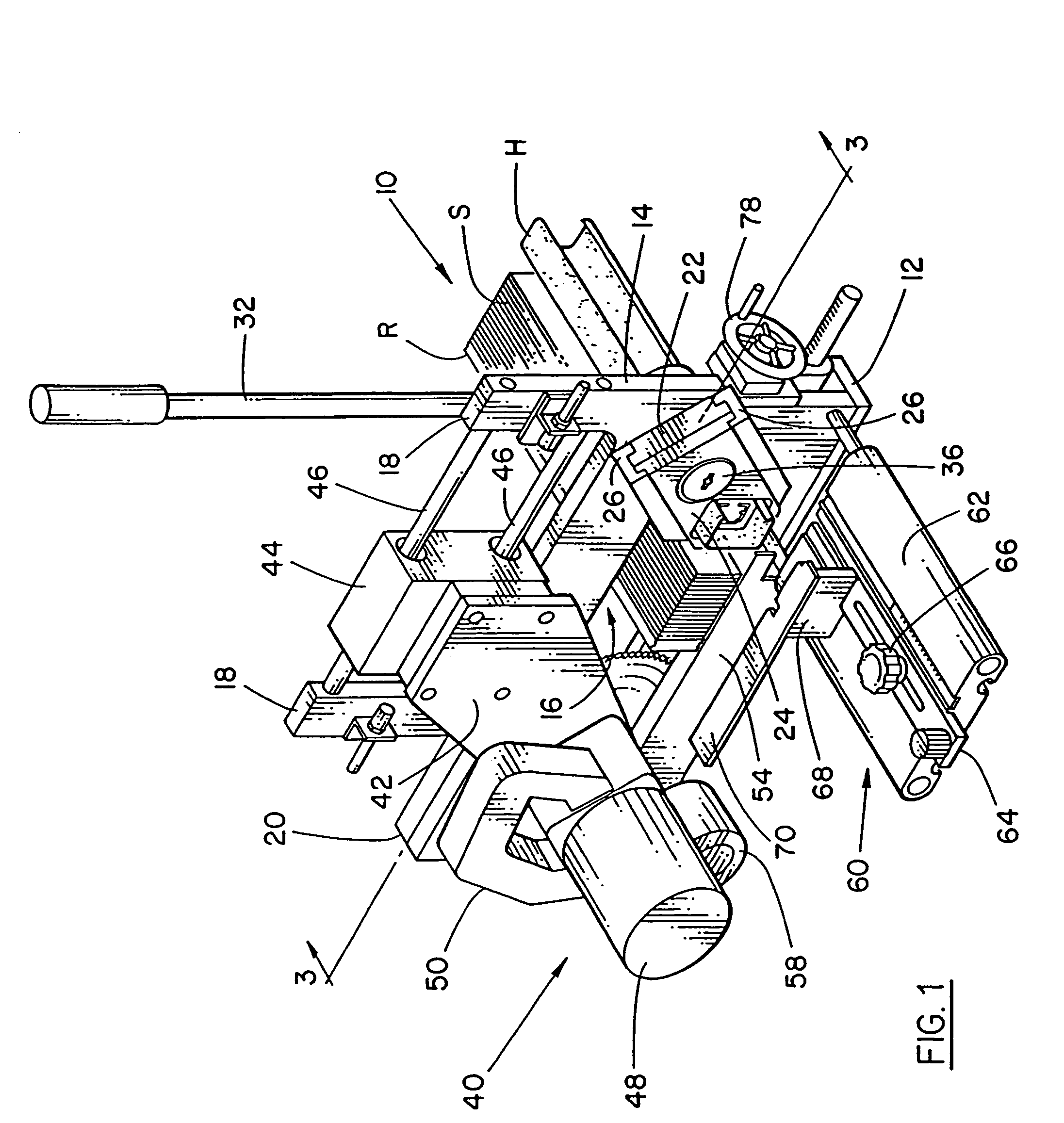
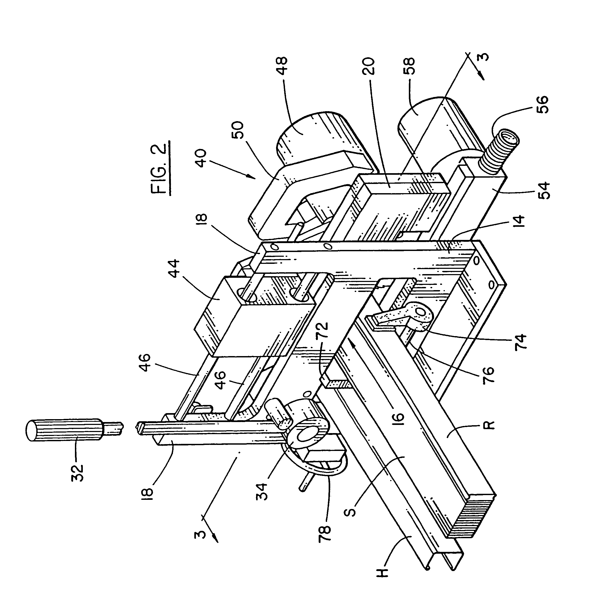
[0054]Referring first of all to FIGS. 1 and 2, the invention is there illustrated in the form of a blind cut down machine indicated generally as 10. Such a machine is intended to be installed at a retail store, and would be bolted on a working surface somewhere in a service area away from the customers.

[0055]As explained above the purpose of the apparatus 10 is to be capable of trimming the head rail and slats both of horizontal or so called Venetian blinds, and also the head rail and slats of vertical blinds.

[0056]Where a Venetian blind has a bottom rail, then the apparatus is also capable is cutting down the bottom rail, if such a blind has a bottom rail.

[0057]It should also be understood that in the case of Venetian blinds, the Venetian blind is already assembled so that there are so called ladder tapes and also raise cords which are already attached to the slats, and connected to the head rail.

[0058]As a result, when trimming the ends of the blind head rail and slats, in Venetia...


PUM

PropertyMeasurementUnit
lengthaaaaaaaaaa
angleaaaaaaaaaa
movement pathaaaaaaaaaa

Abstract

A blind cut-down apparatus for trimming a blind down to size the blind having at least a head rail component, and blind slats suspended from the head rail, and having a blind holding plate with an opening for holding the components in position for cutting, a slat cutter moveable relative to the holding plate for cutting blind components held in the holding plate, and including a movement device for moving the cutter. Also disclosed is a method of saw cutting ends of blind components in which the blind components are held in a head plate and in which a cutter cuts the components. Also disclosed is a blind cut down machine having a moveable head rail support mounted on a blind holder plate, with a moveable head rail opening in the support, with the support being selectively moveable into and out of position for accommodating various types of head rail.

Description

[0001]This application is a Continuation in Part of U.S. patent application Ser. No. 09 / 596,956 now abandoned, title Rotary Saw Cutter Blade Cut Down Machine, inventor Norbert Marocco. Assigned to Shade-O-Matic Ltd., which was a Continuation in Part of U.S. patent application Ser. No. 09 / 360,316 now U.S. Pat. No. 6,336,388, title Rotary Saw Cutter Blade Cut Down Machine, inventor Norbert Marocco. Assigned to Shade-O-Matic Ltd.FIELD OF THE INVENTION[0002]The invention relates to a machine for trimming the ends of blinds and window coverings, in which the slats are formed of materials requiring a saw cut.BACKGROUND OF THE INVENTION[0003]Blinds and window coverings are available in a variety of materials. Horizontal blinds are available in which the head rail, and in some cases, the bottom rails are formed of metal, usually steel, and in which the slats are formed of wood. In other cases slats may be formed of materials such as thick thermo plastic or other heavier materials.[0004]In s...

Claims


Application Information

Patent Timeline
Patent Type & Authority Patents(United States)
IPC IPC(8): B23D23/00B23D45/00B23D45/02B23D47/00E06B9/266
CPCB23D45/003E06B9/266B23D47/005B23D45/02Y10T83/04Y10T83/0586Y10T83/408Y10T83/75Y10T83/8736Y10T83/8748Y10T83/889
Inventor MAROCCO, NORBERT
Owner SHADE O MATIC
Why Eureka
Try Eureka