
Powered patio pole umbrella

a technology for patio poles and umbrellas, applied in umbrellas, coupling devices, gymnastics, etc., can solve the problems of occupying usable space, cumbersome routing of power cords to, from and around patio pole umbrellas, and potential hazards,

Inactive Publication Date: 2006-03-28
VENDOR DEVMENT GROUP
View PDF45 Cites 51 Cited by
  • Summary
  • Abstract
  • Description
  • Claims
  • Application Information

AI Technical Summary

Benefits of technology

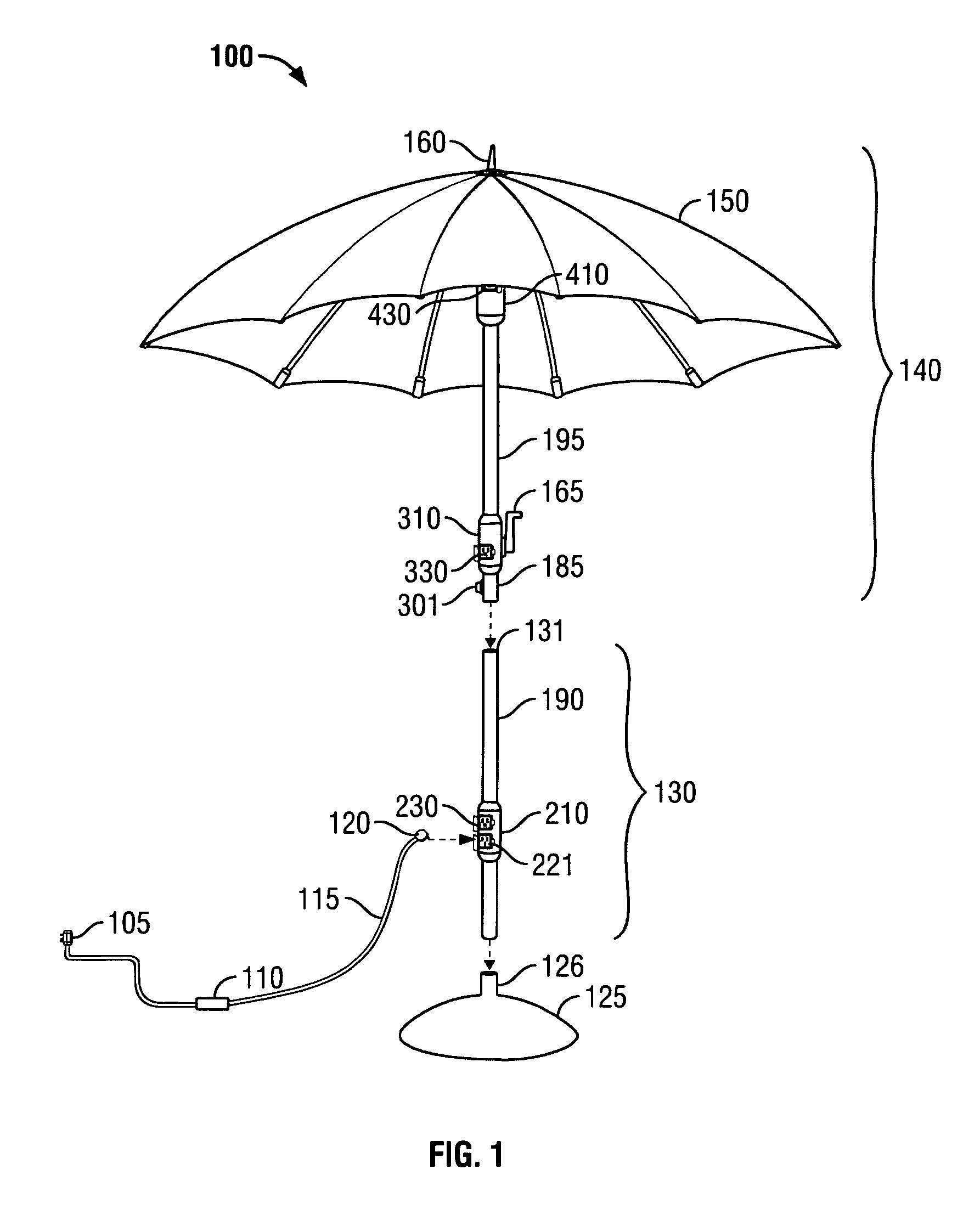
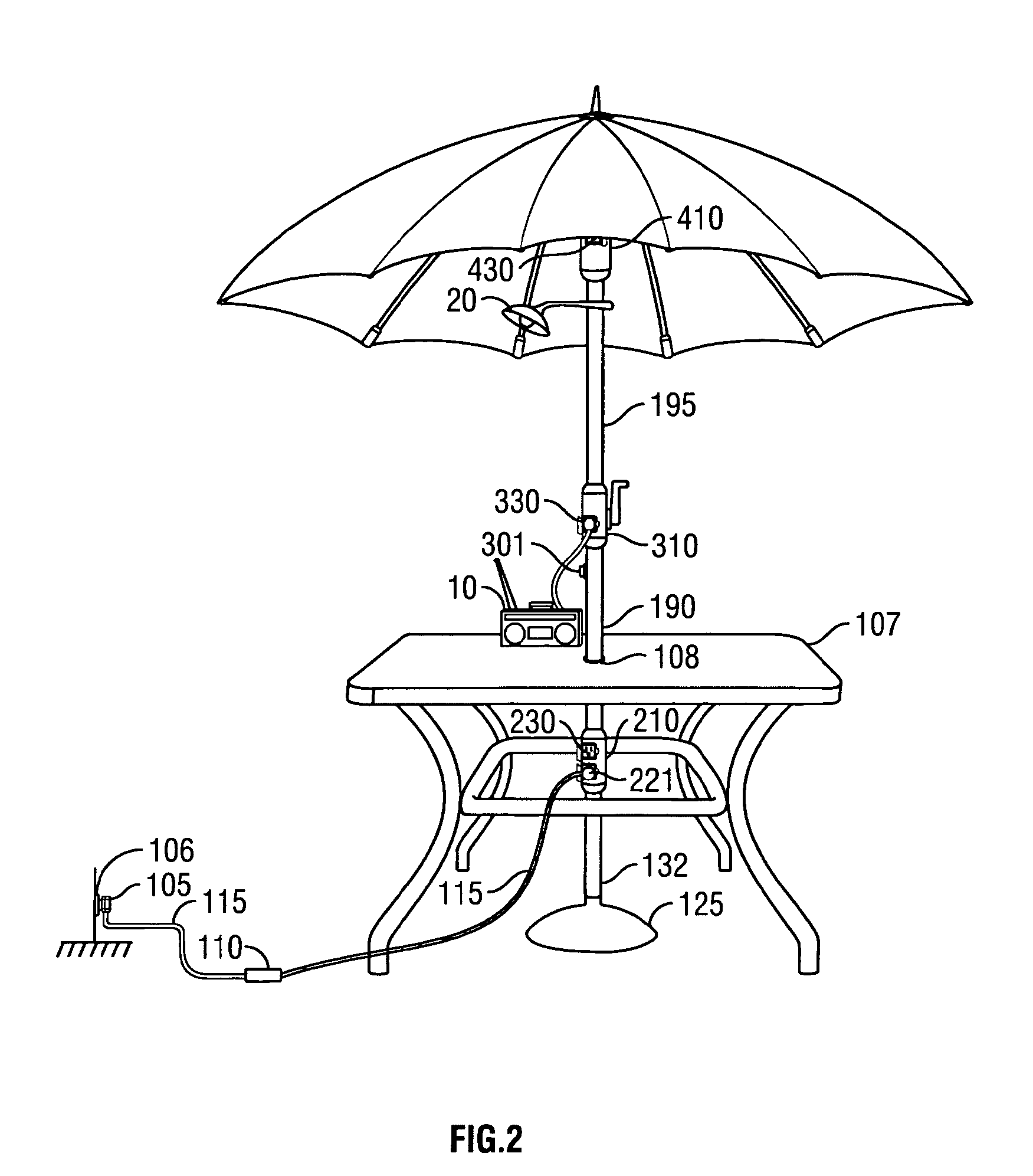
[0018]A preferred embodiment of the present invention provides a powered patio pole umbrella. Power is received by the powered patio pole umbrella from a wall outlet through a cord equipped with a ground fault circuit interrupter. The cord plugs into a bi-directional power hub located in the lower portion of the central pole of the powered patio pole umbrella, but displaced vertically upward from the ground. Power is then supplied from the bi-directional power hub to a plurality of other power hubs located vertically along the powered patio pole umbrella. The power hubs are sealed for moisture and the ground fault circuit interrupter is provided for additional safety

Problems solved by technology

Because such devices require electricity, routing power cords to, from, and around the patio pole umbrella may become cumbersome.
Multiple power cords lying around the patio pole take up usable space and present a potential hazard.
While some consumers choose to strap a power cord to the pole, affixing the power cords to the pole in such a manner does not provide for mobility of the electrical devices attached to the power cords or flexibility in changing from the use of electrical one device to another.
Also, affixing power cords to the pole does nothing to reduce the number of power cords running around the base of the patio umbrella.
Thus, simply securing power cords near the pole of the patio pole umbrella does not provide an optimal solution to management of power cords and wires where an individual desires to alternate the use of various electrical devices near a patio pole umbrella.
Having numerous power cords strewn across the yard, draped over the edges of the patio table, and hanging from above poses an inconvenient and hazardous situation.
The more power cords that are running across the yard and on top of the table, the greater the chances that someone will accidentally stumble over a power cord and / or get snagged on a power cord.
Not only could people get hurt by stumbling over the power cords or snagging the power cords, but the electrical devices attached to power cords could be damaged, as well.
Either condition may lead to potentially dangerous shock or electrocution conditions.
Such a scenario becomes more likely when the cord or power strip are subjected to rain or are near a pool area where splashing may occur.

Method used


Image

  • Powered patio pole umbrella
  • Powered patio pole umbrella
  • Powered patio pole umbrella

Examples


Embodiment Construction

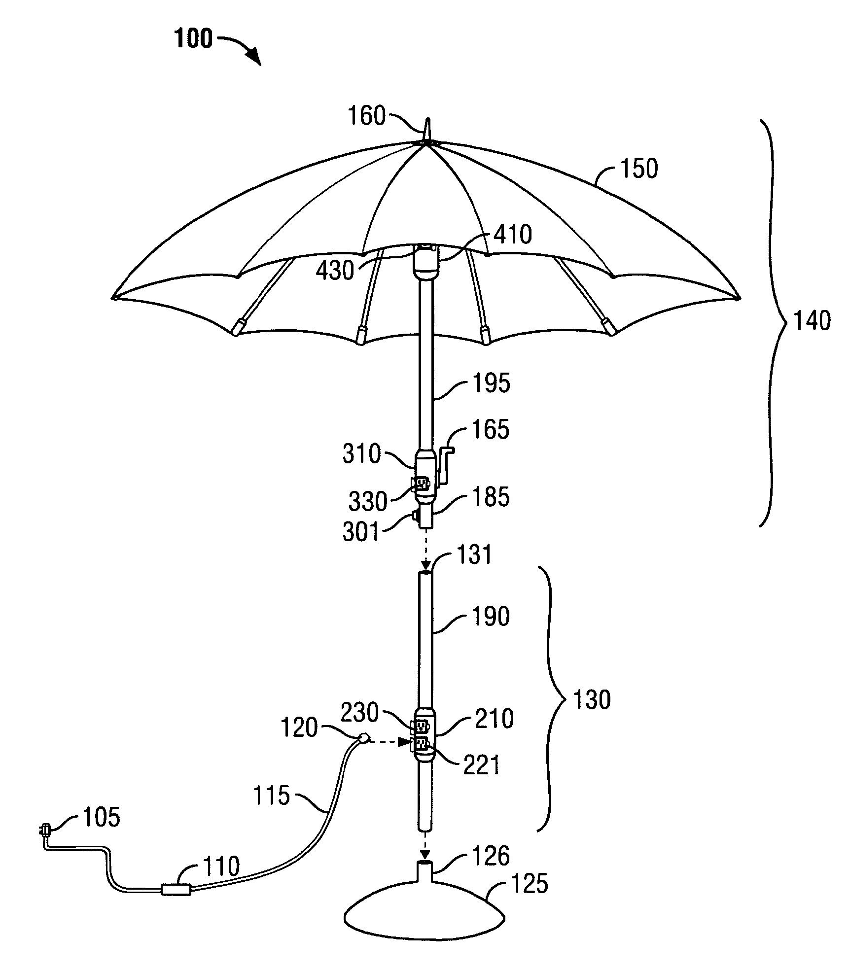
[0051]FIG. 1 illustrates a powered patio pole umbrella 100 in accordance with an embodiment of the present invention. The powered patio pole umbrella 100 includes a power cord 115, support base 125, a powered bottom pole section 130, and a powered top pole section 140. The support base 125 includes a support aperture 126. The powered bottom pole section 130 includes a pole connection aperture 131, a bottom tube 190, a bi-directional power hub 210, an input power receptacle 221, and a bottom power outlet 230. The powered top pole section 140 includes an umbrella canopy 150, an umbrella cap 160, an umbrella crank handle 165, a pole connection piece 185, a top tube 195, a pole section slip restraint 301, a mid-level power hub 310, a mid-level power outlet 330, a top power hub 410, and a top power outlet 430. The power cord 115 includes an outlet plug 105, a male power input connector 120, and a ground fault circuit interrupter 110.

[0052]The bottom tube 190 of the powered bottom pole se...


PUM


Abstract

A powered patio pole umbrella is provided. The powered patio pole umbrella receives power from an external outlet and provides power to a plurality of power hubs including electrical outlets positioned vertically within the central pole of the umbrella. Consumers may plug electrical devices into the electrical outlets in the power hubs. The power hubs are sealed for moisture and a ground fault circuit interrupter is provided for additional safety.

Description

CROSS-REFERENCE TO RELATED APPLICATIONS[0001]The present application is a nonprovisional application which claims the benefit of U.S. Provisional Application No. 60 / 448,704, filed Feb. 18, 2003, entitled “Power Pole Patio Umbrella” and U.S. Provisional Application No. 60 / 541,526, filed Feb. 3, 2004, also entitled “Power Pole Patio Umbrella.”BACKGROUND OF THE INVENTION[0002]The present invention generally relates to a patio pole umbrella. More particularly, the present invention relates to a powered patio pole umbrella with electrical outlets for powering appliances, lights, and other devices.[0003]Patio pole umbrellas are currently in wide use by consumers in a variety of applications and settings. A patio pole umbrella is typically installed outdoors to provide shade on a sunny day or shelter from rain on an overcast day. Individuals may sit under the patio pole umbrella by itself, but frequently the patio pole umbrella is installed with a patio table or serving center.[0004]When u...

Claims


Application Information

Patent Timeline
Patent Type & Authority Patents(United States)
IPC IPC(8): A45B3/02A45B3/00A45B3/04A45B23/00A45B25/14A45B25/18H01H83/02H01R13/52H01R13/713H01R24/00H01R25/00
CPCA45B3/00H01R13/5213H01R25/006A45B23/00A45B25/14A45B2023/0012Y10S135/91A45B2200/1063H01R13/713A45B2025/146
Inventor NIPKE, MIKE
Owner VENDOR DEVMENT GROUP
Learn More