Shed forming mechanism and weaving loom equipped with such a mechanism

a technology of forming mechanism and weaving loom, which is applied in the field ofshed forming mechanism and to weaving loom equipped with such a mechanism, can solve problems such as the compactness of the mechanism, and achieve the effects of reducing the amplitude of the movement of the mobile parts, high precision, and precise positioning of the electromagn

Active Publication Date: 2006-03-28
STAUBLI LYON
View PDF10 Cites 10 Cited by
  • Summary
  • Abstract
  • Description
  • Claims
  • Application Information

AI Technical Summary

Benefits of technology

[0008]Thanks to the invention, the two-part nature of the mobile hooks, of which the body is advantageously made of synthetic material, makes it possible to benefit from the robustness of the body for the mechanical link between the hook and the knife, while the geometry of the metal blade is defined with high precision, this rendering the interactions between the mobile hook and the selection device highly reliable. As the metal blade is fixed on the body in the lower part when the hook is in configuration of operation of the mechanism, the flexibility of the blade, over substantially the whole of its height, may be used for the transverse displacement of its part more particularly intended to come into engagement with a corresponding part of the selection device. The fact that a relative clearance is possible between the blade and the body of the hook may come from the suppleness of the blade and / or from that of the body.
[0010]In particular, the electromagnet of the selection device may be molded in one of the sides of a box for receiving and for guiding the mobile hook in translation. Such molding induces a precise positioning of the electromagnet with respect to the other functional parts of the device, such as the pins of the retaining levers, the stops and the bearings of these levers, as well as grooves for guiding the mobile hooks. Due to this high precision, the amplitudes of the movements of the mobile parts may be reduced, particularly concerning the oscillation of the retaining levers and the bending of the blades of the mobile hooks. This also contributes to the compactness of the mechanism.

Problems solved by technology

This also contributes to the compactness of the mechanism.

Method used


Image

  • Shed forming mechanism and weaving loom equipped with such a mechanism
  • Shed forming mechanism and weaving loom equipped with such a mechanism
  • Shed forming mechanism and weaving loom equipped with such a mechanism

Examples


first embodiment

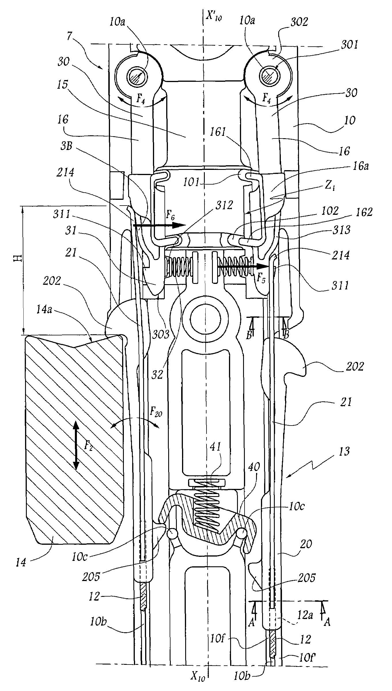
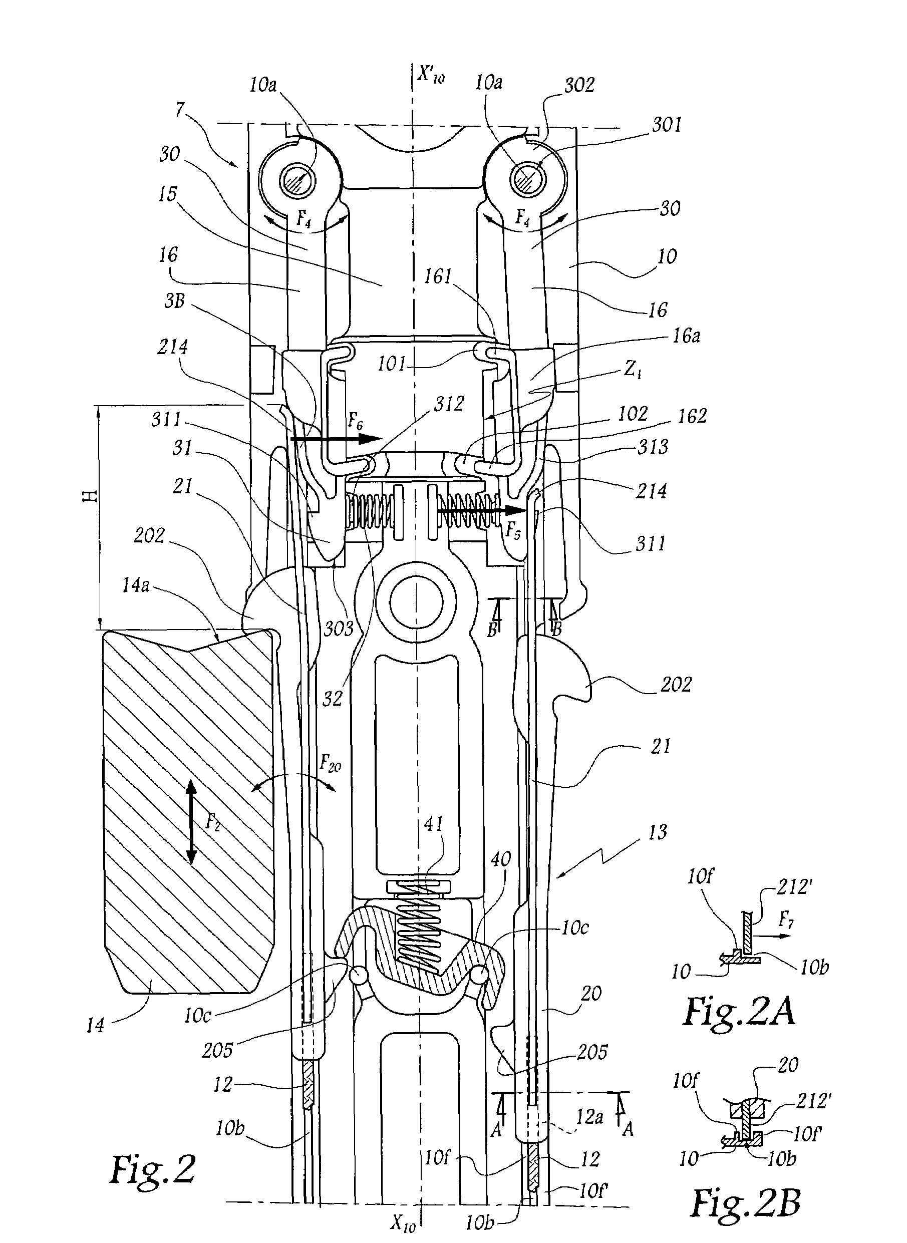
[0047]In the second form of embodiment of the invention shown in FIG. 5, elements similar to those of the first embodiment bear identical references. As previously, knives 14 make it possible selectively to displace mobile hooks 13 each comprising a body 20 made of synthetic material and an elastic metal blade 21 which essentially extends above the zone where it is fixed to this body. Retaining levers 16 are associated with an electromagnet 15.

[0048]In this embodiment, the levers 16 are mounted to pivot about pins 10a fixed with respect to a box 10. The technical teaching of EP-A-0 577 524 is applied here, insofar as the box 10 comprises partitions 10d making it possible to isolate the electromagnet 15 from the ambient atmosphere. Each lever 16 is mounted to pivot on a corresponding pin 10a, as represented by the double arrow F4 and comprises an armature 30 which extends on either side of the pin 10a on which it is mounted. More precisely, each armature 30 comprises a first arm 304 ...

third embodiment

[0053]As in the first form of embodiment, a deflector 161 is provided on each lever 16, between the armature 30 and the pin 10a while a second deflector 162 is provided between the armature 30 and that part of the body 31 intended to interact with the blade 21 of a hook 13. The deflector 162 of this third embodiment may move inside a groove 102 made in the box 10 between the positions respectively shown to the left and to the right of FIG. 6. This deflector 162 projects with respect to the principal part 16a of the lever 16 both in the direction of the median axis X10–X′0 of the box 10 and opposed thereto, with the result that the circulation of flock or of dust is prevented both between the lever 16 and the electromagnet 15 and between the lever 16 and the outer web 10g of the box 10.

[0054]In addition, and as is more particularly visible in FIG. 6A, the deflector 162 also projects perpendicularly to the plane of FIG. 6 with respect to the principal part 16a of the lever 16, this al...


PUM


Abstract

Hooks for controlling movement of heddle cords in a Jacquard weaving loom are each displaced by a knife, between a position of top dead center, wherein each hook may be immobilized by a selection device, and a position of bottom dead center. Each hook includes a body provided with a catch that engages a corresponding knife and a metal blade that is relatively movable with respect to portions of the body adjacent the catch and that interacts with the selection device to selectively retain the hook in the top dead position thereof.

Description

BACKGROUND OF THE INVENTION[0001]1. Field of the Invention[0002]The present invention relates to a shed forming mechanism and to a weaving loom equipped with such a mechanism.[0003]2. Brief Description of the Related Art[0004]In a Jacquard type weaving loom, a shed forming mechanism selectively lifts heddles, each comprising an eye in which a warp yarn passes, this yarn being located, as a function of the position of a hook to which the upper end of the heddle is fixed, above or below a weft yarn displaced by the loom. Such a known mechanism, for example disclosed by EP-A-0 219 437, comprises, inter alia, mobile hooks each provided with a lateral catch capable of cooperating with knives animated by vertical reciprocating movements in phase opposition. Each mobile hook is provided with a curved end allowing it to be immobilized by cooperation of shapes with a retaining lever.[0005]Each mobile hook is also provided with an elastic tongue in one piece with the hook and intended to cont...

Claims


Application Information

Patent Timeline
Patent Type & Authority Patents(United States)
IPC IPC(8): D03C3/00D03C1/00D03C3/06D03C3/20D03C3/24
CPCD03C3/06D03C3/24D03C3/20D03C3/00
Inventor BASSI, DARIOBOUCHET, DAMIEN
Owner STAUBLI LYON
Why Eureka
Try Eureka