Positioning device of a nail driver

a positioning device and nail driver technology, applied in the field of nail drivers, can solve the problems of not being able to control the angle of the beating of the nail, the nail cannot be well positioned, and the probe head and the guide block cannot be well controlled to beat the nail vertically, so as to achieve the effect of simple structure and low cos

Inactive Publication Date: 2006-03-28
BESCO PNEUMATIC CORP
View PDF11 Cites 29 Cited by
  • Summary
  • Abstract
  • Description
  • Claims
  • Application Information

AI Technical Summary

Benefits of technology

[0008]Accordingly, the primary object of the present invention is to provide a positioning device of a nail driver, wherein the size of the nail output opening is adjusted elastically with the nail tip, nail body and the nail head. Thereby, the direction of the nail is calibrated in the shooting process. The present invention has a simple structure and is made with a lower cost.

Problems solved by technology

Although the nail can be shoot steadily, but the beating direction cannot be well controlled to be at a desired angle.
Furthermore, when the probe head is collided by the nails repeatedly.
It will get elastic fatigue so that the nail cannot be well positioned.
The probe head and the guide block can not be well controlled to beat the nail vertically due to the difficulty in controlling the beating force, while the positioning structure is not a strict symmetrical structure.
The prior art positioning device of a nail driver has a very complicate structure.
Not only the assembly cost is high, but also the fault ratio of the product is high.

Method used


Image

  • Positioning device of a nail driver
  • Positioning device of a nail driver
  • Positioning device of a nail driver

Examples


Embodiment Construction

[0018]In order that those skilled in the art can further understand the present invention, a description will be described in the following in details. However, these descriptions and the appended drawings are only used to cause those skilled in the art to understand the objects, features, and characteristics of the present invention, but not to be used to confine the scope and spirit of the present invention defined in the appended claims.

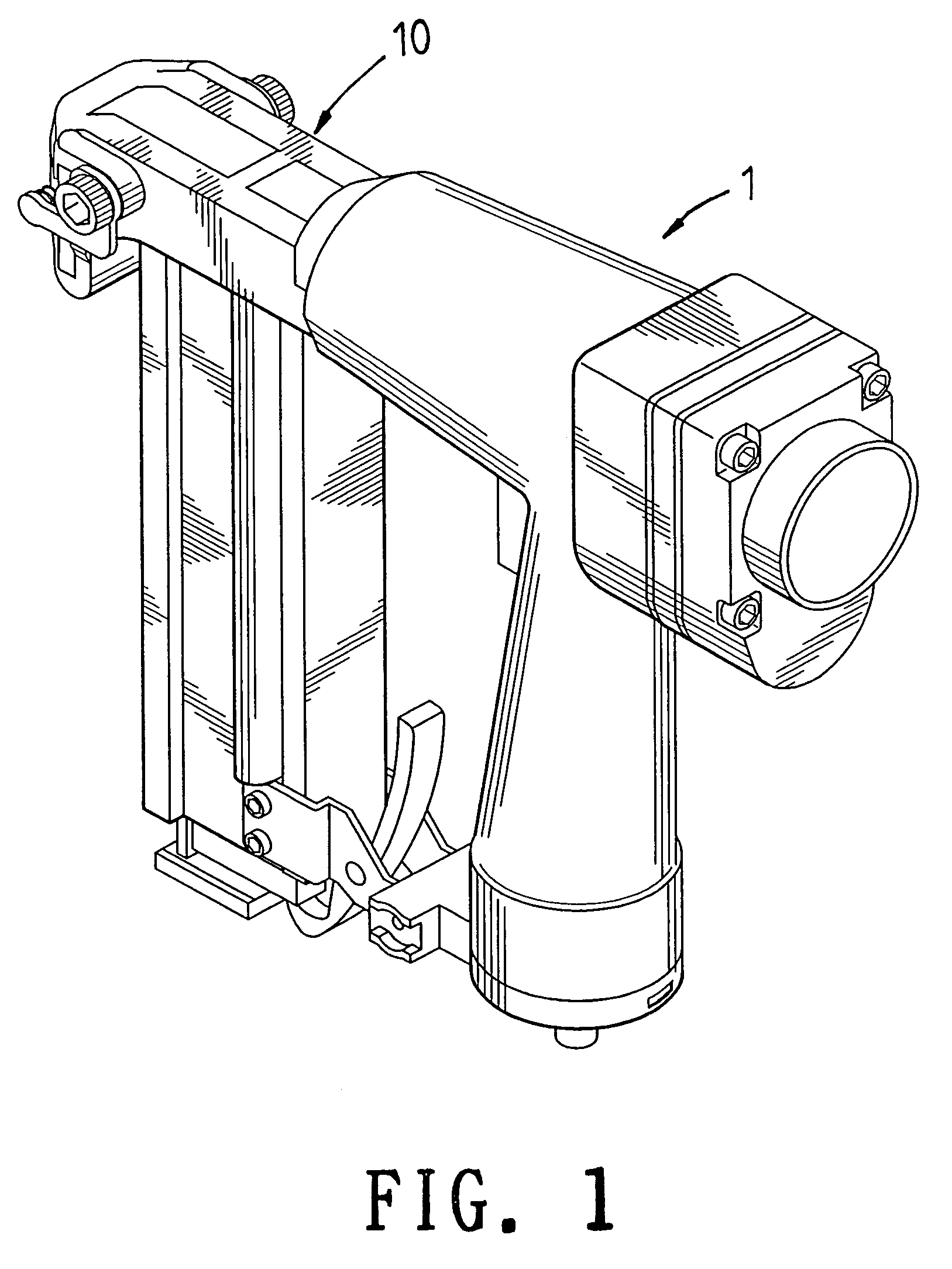
[0019]With reference to FIGS. 1 and 2, the positioning device of a nail driver of the present invention is illustrated. The positioning device has the following elements.

[0020]A tool body 1 is used in the prior art and thus the details will not be described herein.

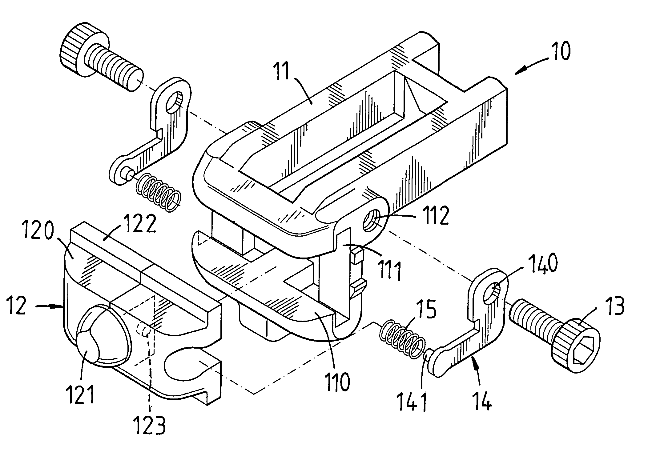
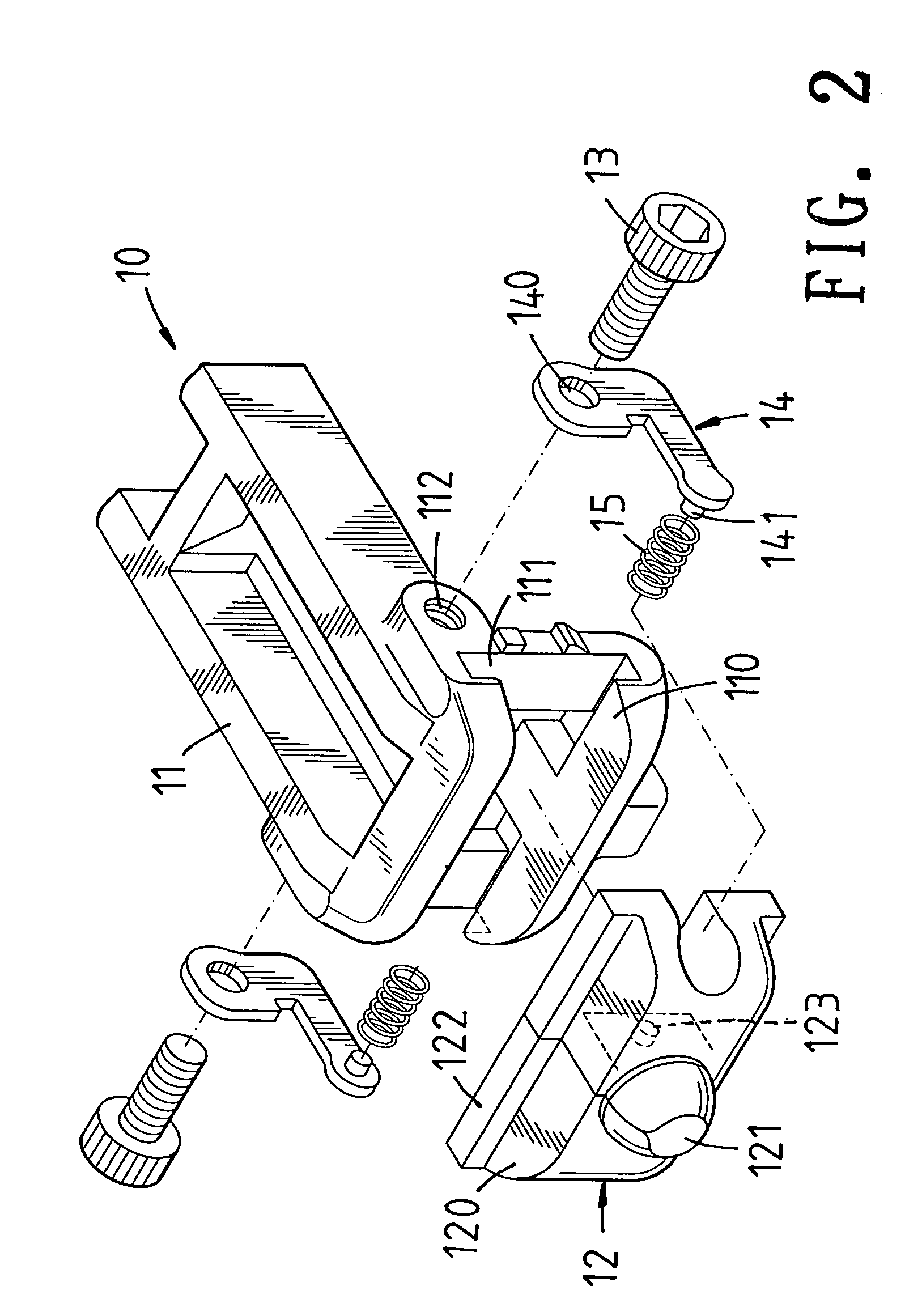
[0021]A positioning unit 10 is installed at a front end of the tool body 1. The positioning unit 10 has a nail output frame 11, a guide block 12, two screw units 13, two positioning plates 14, and two spring elements 15.

[0022]The rear end of the nail output frame 11 is connected to a too...


PUM


Abstract

A positioning device of a nail driver comprises a tool body; a positioning unit in a front end of the tool body; the positioning unit having a nail output frame and a guide block formed by two sliding blocks; an nail output opening at a front end of the nail output frame formed with two sliding recesses; the two sliding blocks being movable installed into the sliding recesses; a guide opening formed between the two sliding blocks; when the two sliding blocks are separated, the guide opening expands; two positioning plates; each of two sides of the nail output frame having a respective one of the two positioning plates; and two spring elements, each spring element being confined by a respective one of the two positioning plates and a respective one of the two sliding blocks.

Description

FIELD OF THE INVENTION[0001]The present invention relates to nail drivers, and particular to a positioning device of a nail driver, wherein the size of the nail output opening is adjusted elastically with the nail tip end, nail body and the nail head. Thereby, the direction of the nail is calibrated in the shooting process. The present invention has a simple structure and is made with a lower cost.BACKGROUND OF THE INVENTION[0002]Pneumatic or electromotive nail drivers are more and more popular due the easy operation and steady power supplying properties thereof.[0003]In U.S. Pat. No. 5,238,167 and U.S. Pat. No. 5,452,835, nail drivers are disclosed. In that, the nail output opening of a nail driver has a probe head. A top of the probe head serves as a reference of the nail triggering unit. The probe head is elastic and is turnable in a small range. When the nail is ejected to move forwards, the probe head will be ejected away. Thereby, in triggering, the nail is pushed by the probe...

Claims


Application Information

Patent Timeline
Patent Type & Authority Patents(United States)
IPC IPC(8): B25C7/00
CPCB25C1/188
Inventor PENG, WEI-CHIH
Owner BESCO PNEUMATIC CORP
Why Eureka
Try Eureka