Power control circuit with reduced power consumption

a power control circuit and power consumption technology, applied in the direction of power consumption reduction, pulse technique, instruments, etc., can solve the problems of increasing the difficulty of turning on the transistor, the leakage current (subthreshold current) the tendency to increase the leakage current of the transistor while it is not in operation, so as to reduce the cost of the product, and reduce the power consumption of the semiconductor integrated circui

Inactive Publication Date: 2006-03-28
SOCIONEXT INC
View PDF19 Cites 5 Cited by
  • Summary
  • Abstract
  • Description
  • Claims
  • Application Information

AI Technical Summary

Benefits of technology

[0009]It is an object of the present invention to reduce power consumption of a semiconductor integrated circuit during its standby period. More particularly, the object is to reduce the power consumption of the semiconductor integrated circuit during the standby period without complicating its device structure. Further, the object is to reduce the power consumption of the semiconductor integrated circuit during the standby period without increasing its product cost.

Problems solved by technology

When the power supply voltage becomes lower and a difference between the power supply voltage and a threshold voltage of a transistor becomes smaller, difficulty in turning on the transistor increases and its operating speed decreases.
Moreover, accompanying microfabrication of the transistor, a leakage current (subthreshold current) of the transistor while it is not in operation has a tendency to increase.
Therefore, the increase in the power consumption is a significant problem in portable equipment using batteries.
However, when an integration degree of the semiconductor integrated circuit increases accompanying the microfabrication of the element structure of the semiconductor, the power consumption is not reduced enough due to the subthreshold current of the switch transistor, even though the MTCMOS technology is employed.

Method used


Image

  • Power control circuit with reduced power consumption
  • Power control circuit with reduced power consumption
  • Power control circuit with reduced power consumption

Examples


Embodiment Construction

[0035]Hereinafter, preferred embodiments of the present invention will be explained with reference to the drawings.

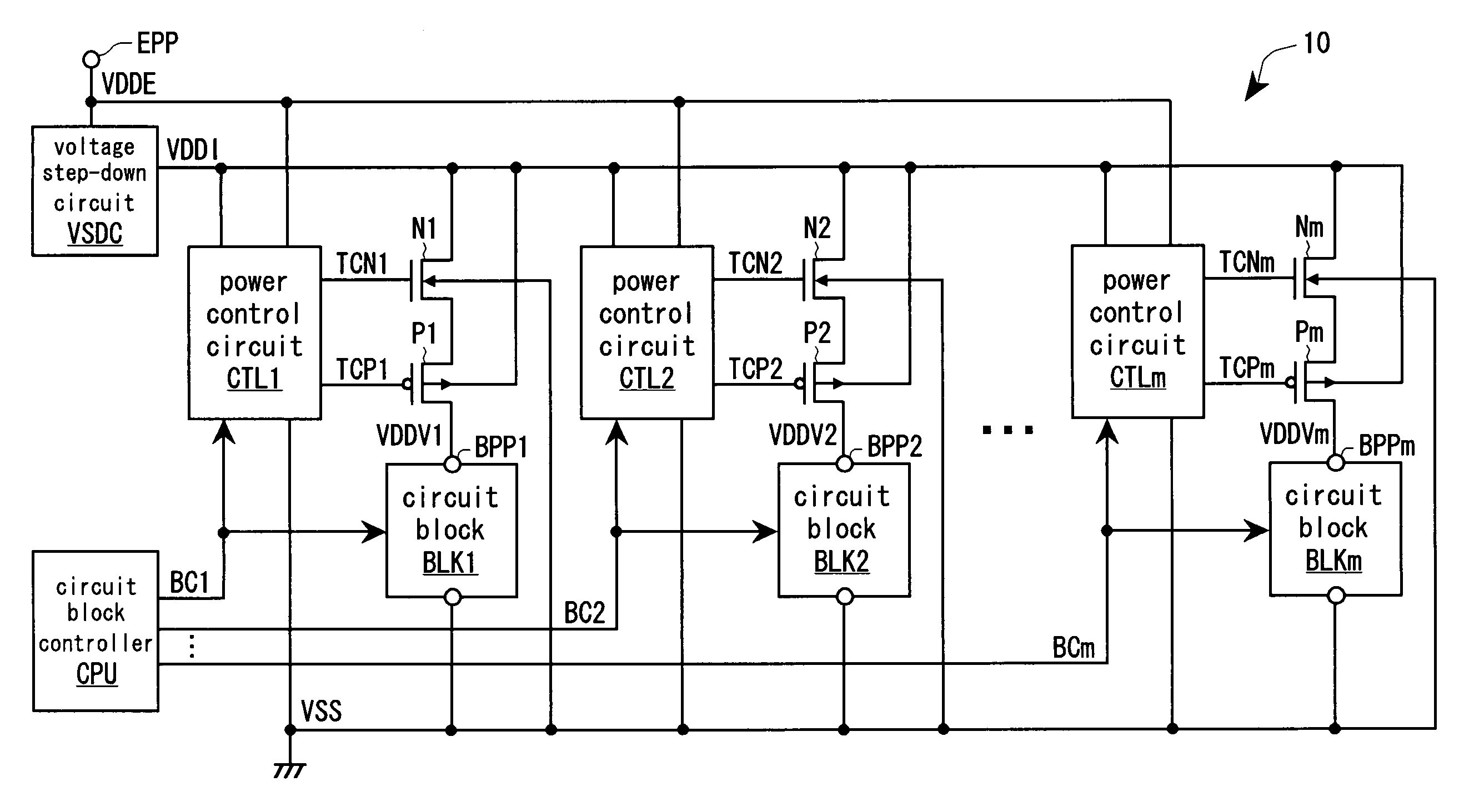
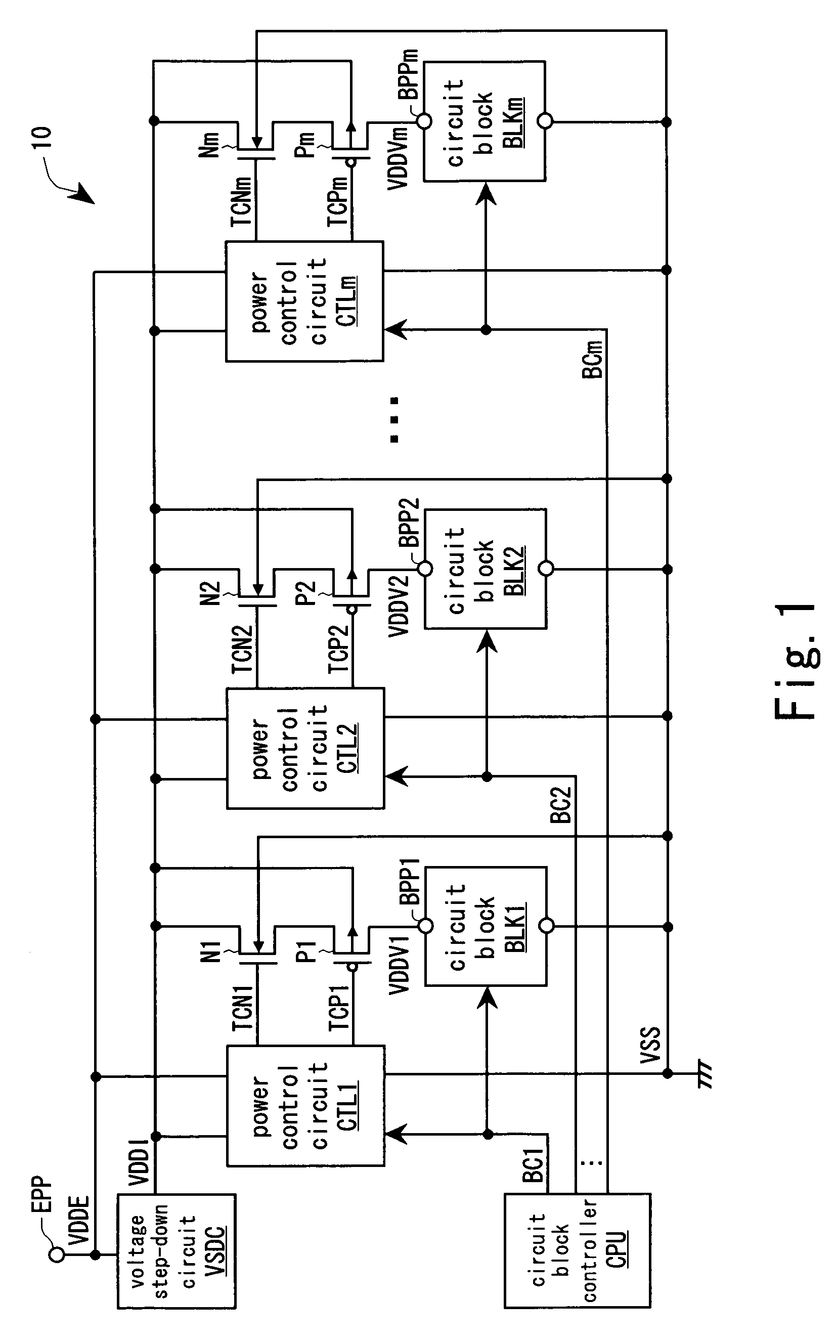
[0036]FIG. 1 shows an embodiment of a semiconductor integrated circuit according to the present invention. In the following explanation, the same numerals and symbols as power supply lines are given to designate voltages supplied to the power supply lines.

[0037]A semiconductor integrated circuit 10 includes a voltage step-down circuit VSDC, a circuit block controller CPU, power control circuits CTL (CTL1 to CTLm), circuit blocks BLK (BLK1 to BLKm), nMOS transistors (first conductive transistors) N (N1 to Nm), pMOS transistors (second conductive transistors) P (P1 to Pm), a first actual power supply line VDDI, a second actual power supply line VDDE, virtual power supply lines VDDV (VDDV1 to VDDVm), and a ground line VSS. Incidentally, structures of the power control circuits CTL2 to CTLm, the circuit blocks BLK2 to BLKm, the nMOS transistors N2 to Nm, the pMOS transistor...


PUM


Abstract

A first conductive transistor having a high threshold value and a second conductive transistor having a low threshold value are connected in series between a first actual power supply line supplying a power supply voltage and a virtual power supply line connected to a power supply pin of a circuit block constituted of transistors having a low threshold value. The first and second conductive transistors have polarities which are opposite to each other. A power control circuit turns on the first and second conductive transistors while the circuit block is in operation and turning off the first and second conductive transistors while the circuit block is not in operation. Therefore, subthreshold currents of the first and second conductive transistors can be suppressed. As a result of this, it is possible to reduce power consumption of the semiconductor integrated circuit during its standby period.

Description

CROSS-REFERENCE TO RELATED APPLICATIONS[0001]This application is a continuation of PCT International Patent Application No. PCT / JP03 / 02636, filed on Mar. 6, 2003, the entire contents of which are incorporated herein by reference.BACKGROUND OF THE INVENTION[0002]1. Field of the Invention[0003]The present invention relates to a semiconductor integrated circuit having a circuit block constituted of transistors having a low threshold value, to which supply of a power supply voltage is interrupted while it is not in operation.[0004]2. Description of the Related Art[0005]As element structure of a semiconductor becomes finer, a power supply voltage supplied to a semiconductor integrated circuit becomes lower every year. When the power supply voltage becomes lower and a difference between the power supply voltage and a threshold voltage of a transistor becomes smaller, difficulty in turning on the transistor increases and its operating speed decreases. In order to prevent the above problems...

Claims


Application Information

Patent Timeline
Patent Type & Authority Patents(United States)
IPC IPC(8): H03K4/02H01L27/04H01L27/092H03K19/00
CPCH01L27/092H03K19/0016H01L27/0928
Inventor KAKIUCHI, TAKASHI
Owner SOCIONEXT INC
Why Eureka
Try Eureka