Out-of-range detector

Inactive Publication Date: 2006-03-28
KONINKLIJKE PHILIPS ELECTRONICS NV
View PDF6 Cites 16 Cited by
  • Summary
  • Abstract
  • Description
  • Claims
  • Application Information

AI Technical Summary

Benefits of technology

[0009]In one embodiment, the monitoring device provides an alert signal, such as an audible alert or a vibration alert, when the locator signal is not received within a given period of time. The direction indication may change as the orientation of the monitoring device changes such that regardless of the orientation of the monitoring device, the direction indication points in the direction of the last received locator signal. The monitoring device may provide a solicitation signal to the monitored device to solicit the transmission of the locator signal. In this embodiment, the monitored device needs not send the locator signal until after receipt of the solicitation signal. The monitoring device may have a sensitivity adjustment for adjusting the receiving sensitivity of the monitoring device for the locator signal. This provides a user of the monitoring system the ability to readily adjust the distance that the monitoring and monitored device must be apart prior to the monitoring device producing an alert signal.
[0010]Advantageously, the system enables a user of the monitoring device to maintain an awareness of the direction and proximity of the monitored device without requiring the user to maintain constant visual contact of the monitored device. These and other features and advantages of the present invention will become more apparent from the accompanying drawings and the following detailed description.

Problems solved by technology

In this day, it is more and more difficult for an adult to keep an eye on a child.
Unfortunately, it is also at this time that a monitoring adult is most distracted.
Accordingly, it is easy for the monitoring adult to loose sight of the child and thereby, lead to frantic searching of the immediate area to find the child.
A problem exists with this system in that although the adult is alerted that the child is no longer in close proximity, the adult has no idea in which direction the child is located.
However, in an area that has many objects around, such as aisles and sales displays, as in the case of the above-mentioned shopping mall, the child may not be directly viewable from the adults vantage point.
However, typically a GPS device does not transmit location information to a secondary device.
However, this system has many drawbacks in that the system is large and complex and does not lend itself to a simple, cost effective system.
Further, the On-Star™ device does not determine when a monitored device leaves the vicinity of a monitoring device.

Method used


Image

  • Out-of-range detector
  • Out-of-range detector
  • Out-of-range detector

Examples


Embodiment Construction

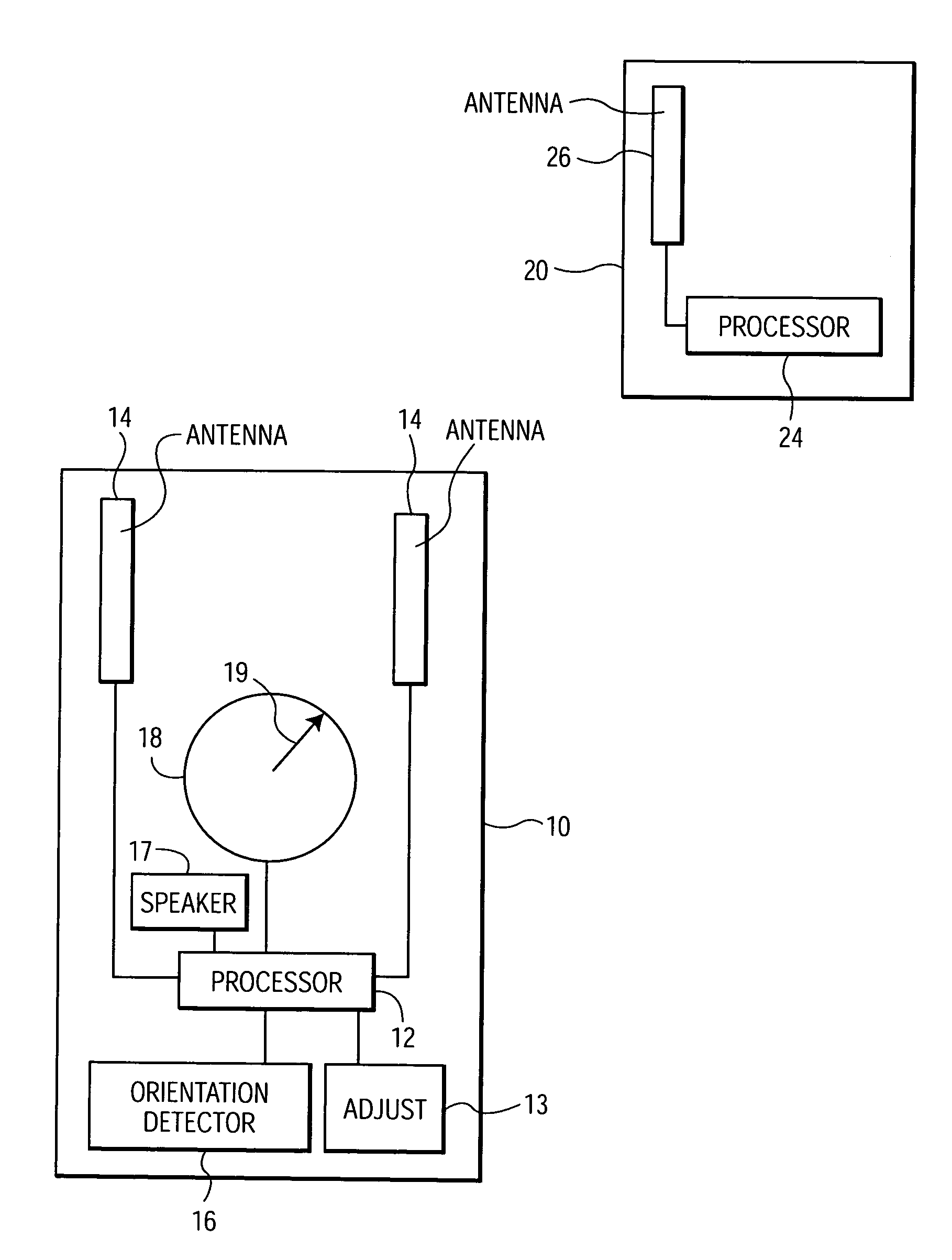
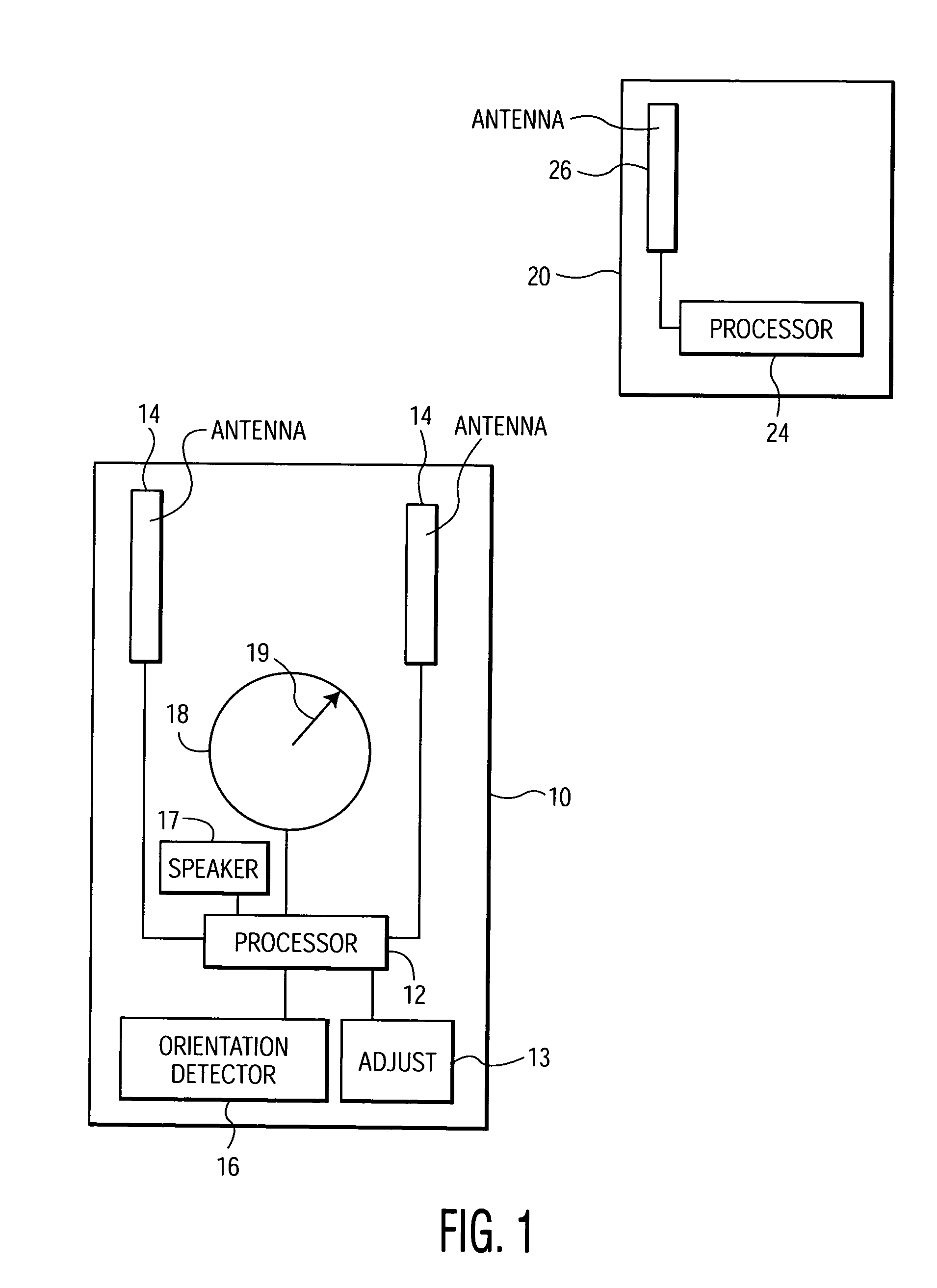
[0013]FIG. 1 shows an example of a system including a monitoring device 10 and a monitored device 20 in accordance with the present invention. The monitoring device 10 is shown having antenna elements 14, for receiving signals transmitted from the monitored device 20. The monitoring device 10 further has a processor 12, a display 18, an orientation detector 16, an alert output 17, such as a speaker, and a sensitivity adjustment 13. The processor 12 is arranged to receive signals from the antennas 14, the orientation detector 16, and the sensitivity adjustment 13 and is arranged to provide signals to the antennas 14, the alert output 17, and the display 18 as further described herein below.

[0014]The monitored device 20 has a processor 24 and an antenna 26. The processor 24 is arranged to transmit and / or receive signals from the antenna 26 and is arranged to provide locator signals that are transmitted to the monitoring device 10 from the antenna 26.

[0015]The processor 12 receives the...


PUM


Abstract

A monitoring system for monitoring a direction of a monitored device when the monitored device is positioned further than a predetermined distance from a monitoring device. The monitoring device receives a locator signal from the monitored device and produces a direction indication that indicates the direction of the received locator signal. If the monitoring device no longer receives the locator signal, the direction indication indicates the direction of the last received locator signal.

Description

FIELD OF THE INVENTION[0001]The present invention generally relates to a method and device for monitoring a monitored device and particularly relates to a method and system for determining when a monitored device leaves a vicinity of a monitoring device.BACKGROUND OF THE INVENTION[0002]In this day, it is more and more difficult for an adult to keep an eye on a child. Children have a strong desire to explore when they are in an environment that has lots of activity or objects around, such as a shopping mall. Unfortunately, it is also at this time that a monitoring adult is most distracted. Accordingly, it is easy for the monitoring adult to loose sight of the child and thereby, lead to frantic searching of the immediate area to find the child. Accordingly, it is desirable to determine when a child leaves the area of an adult that is minding the child.[0003]This desire to determine when the monitored device leaves the vicinity of the monitoring device is not limited to the above paren...

Claims


Application Information

Patent Timeline
IPC IPC(8): G08B1/08A01M31/00G08B13/14G08B21/02
CPCA01M31/002G08B21/0263G08B13/1427
Inventor LU, JIN
Owner KONINKLIJKE PHILIPS ELECTRONICS NV
Why Eureka
Try Eureka