EAS and RFID systems incorporating field canceling core antennas

a field canceling core and antenna technology, applied in the field of electronic article surveillance (eas) and radio frequency identification (rfid) systems, can solve problems such as problems such as the inability of the associated eas or rfid system to meet regulatory requirements, the configuration of field canceling loop antennas does not directly meet the requirements of magnetic core antennas, etc., to achieve the effect of reducing the magnetic field strength

Active Publication Date: 2006-03-28
SENSORMATIC ELECTRONICS CORP
View PDF10 Cites 90 Cited by
  • Summary
  • Abstract
  • Description
  • Claims
  • Application Information

AI Technical Summary

Benefits of technology

[0013]According to another aspect of the invention, there is provided a method of establishing an interrogation zone in an EAS or RFID system with reduced magnetic field strength outside of the interrogation zone. The method includes: exciting a first core antenna to provide

Problems solved by technology

However, if the magnetic field radiates at significant strength levels beyond the interrogation zone, problems can occur.
For instance, the associated EAS or RFID system may not comply with regulatory requirements that restrict the level of the magnetic field at various distances from the antenna(s).
However, the configurations utilized for fi

Method used


Image

  • EAS and RFID systems incorporating field canceling core antennas
  • EAS and RFID systems incorporating field canceling core antennas
  • EAS and RFID systems incorporating field canceling core antennas

Examples


Embodiment Construction

[0032]For simplicity and ease of explanation, the present invention will be described herein in connection with various exemplary embodiments thereof associated with EAS systems. A core antenna system consistent with the present invention may, however, be used in connection with an RFID or other system. It is to be understood, therefore, that the embodiments described herein are presented by way of illustration, not of limitation.

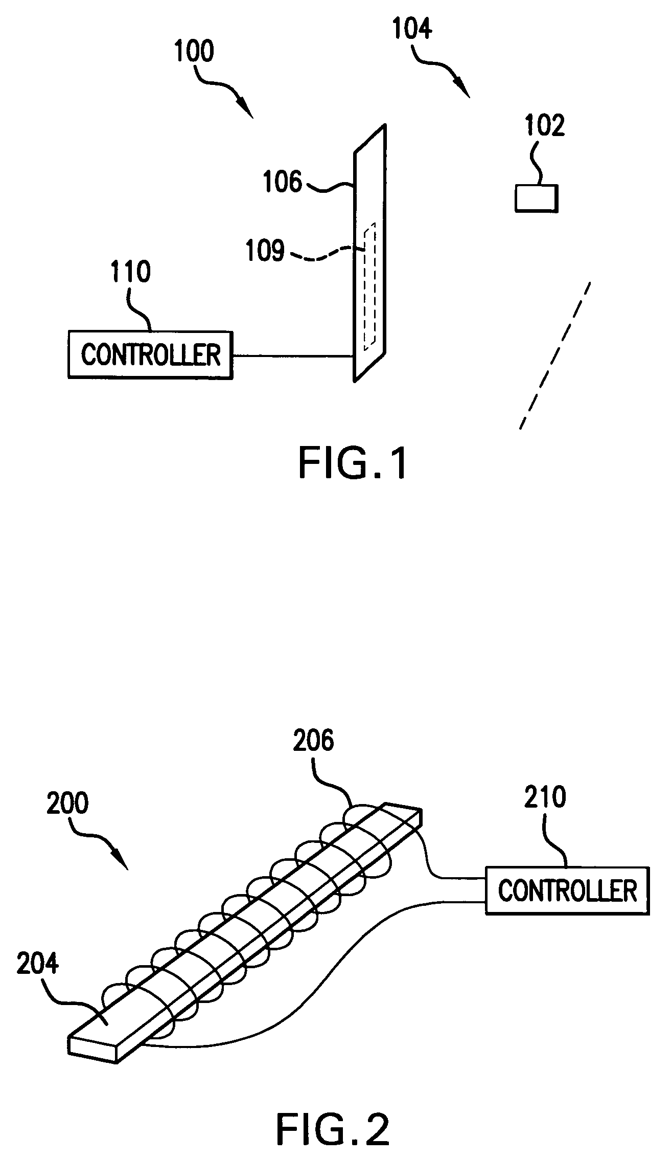
[0033]FIG. 1 illustrates an EAS system 100 including a core antenna system 109 consistent with the invention. The EAS system 100 generally includes a controller 110 and a pedestal 106 for housing the core antenna system 109. The controller 110 is shown separate from the pedestal 106 for clarity but may be included in the pedestal housing as well. In the exemplary embodiment of FIG. 1, the antenna system 109 is configured as a transceiver and the associated controller 110 includes proper control and switching to switch from transmitting to receiving function...


PUM


Abstract

An EAS or RFID system including first and second core antenna systems. The first and second antenna systems establish magnetic fields having opposite directions and are positioned so that the fields at least partially cancel outside of an interrogation zone for detecting an EAS or RFID tag. There is also provided an EAS or RFID wherein the magnetic field direction established by a core antenna is varied at certain time intervals to minimize the effects of null zones in the interrogation zone.

Description

CROSS-REFERENCE TO RELATED APPLICATIONS[0001]This application claims the benefit of U.S. Provisional Application Ser. No. 60 / 478,942, filed Jun. 16, 2003, the teachings of which are incorporated herein by reference.FIELD OF THE INVENTION[0002]The present invention relates to electronic article surveillance (EAS) and radio frequency identification (RFID) systems, and, in particular, EAS and RFID systems incorporating magnetic core antennas.BACKGROUND[0003]EAS and RFID systems are typically utilized to protect and track assets. In an EAS system, an interrogation zone may be established at the perimeter, e.g. at an exit area, of a protected area such as a retail store. The interrogation zone is established by an antenna or antennas positioned adjacent to the interrogation zone. The antenna(s) establish an electromagnetic field of sufficient strength and uniformity within the interrogation zone. EAS markers are attached to each asset to be protected. When an article is properly purchase...

Claims


Application Information

Patent Timeline
IPC IPC(8): G08B13/14G06K7/08G08B13/24H01Q1/22H01Q3/26H01Q3/30H01Q7/00H01Q7/04H01Q7/06H01Q21/29
CPCG06K7/10316G06K7/10336G08B13/2474H01Q1/22H01Q1/2216H01Q21/29H01Q3/30H01Q7/00H01Q7/04H01Q7/06H01Q3/26
Inventor HALL, STEWART E.BALCH, BRENT F.COPELAND, RICHARD L.
Owner SENSORMATIC ELECTRONICS CORP
Why Eureka
Try Eureka