Electric rotating machine

a rotating machine and rotating shaft technology, applied in the direction of magnetic circuit rotating parts, magnetic circuit shape/form/construction, association with control/drive circuits, etc., can solve problems such as malfunction and erroneous detection of the position of the rotor, and achieve the effect of preventing malfunction of the rotational position detector

Active Publication Date: 2009-01-20
MITSUBISHI ELECTRIC CORP
View PDF19 Cites 14 Cited by
  • Summary
  • Abstract
  • Description
  • Claims
  • Application Information

AI Technical Summary

Benefits of technology

[0007]The present invention was made to solve the problems as mentioned above, and has an object of providing an electric rotating machine in which a rotational position detector is not affected by the external magnetic field, and noises included in the outputs from the rotational position detector are reduced to prevent malfunction of the rotational position detector.
[0009]In the electric rotating machine of above construction according to the invention, since there is provided a shield member that covers the circumference of a rotational position detector and that shields the external magnetic field, most of magnetic fields that are generated outside the rotational position detector are absorbed into the shield member, and the magnetic field strength around the rotational position detector comes to be significantly small. Thus, the noises to be superimposed on outputs from the rotational position detector are decreased to such a levels as causing no malfunction of the rotational position detector.

Problems solved by technology

When operating the switching element, sharp magnetic field change occurs accompanied by the rapid change of currents, and therefore such magnetic field change comes out as electromagnetic noises in other devices or circuits, which may lead to the occurrence of malfunction.
Consequently, a problem exists that the position of the rotor is erroneously detected.

Method used


Image

  • Electric rotating machine
  • Electric rotating machine
  • Electric rotating machine

Examples


embodiment 1

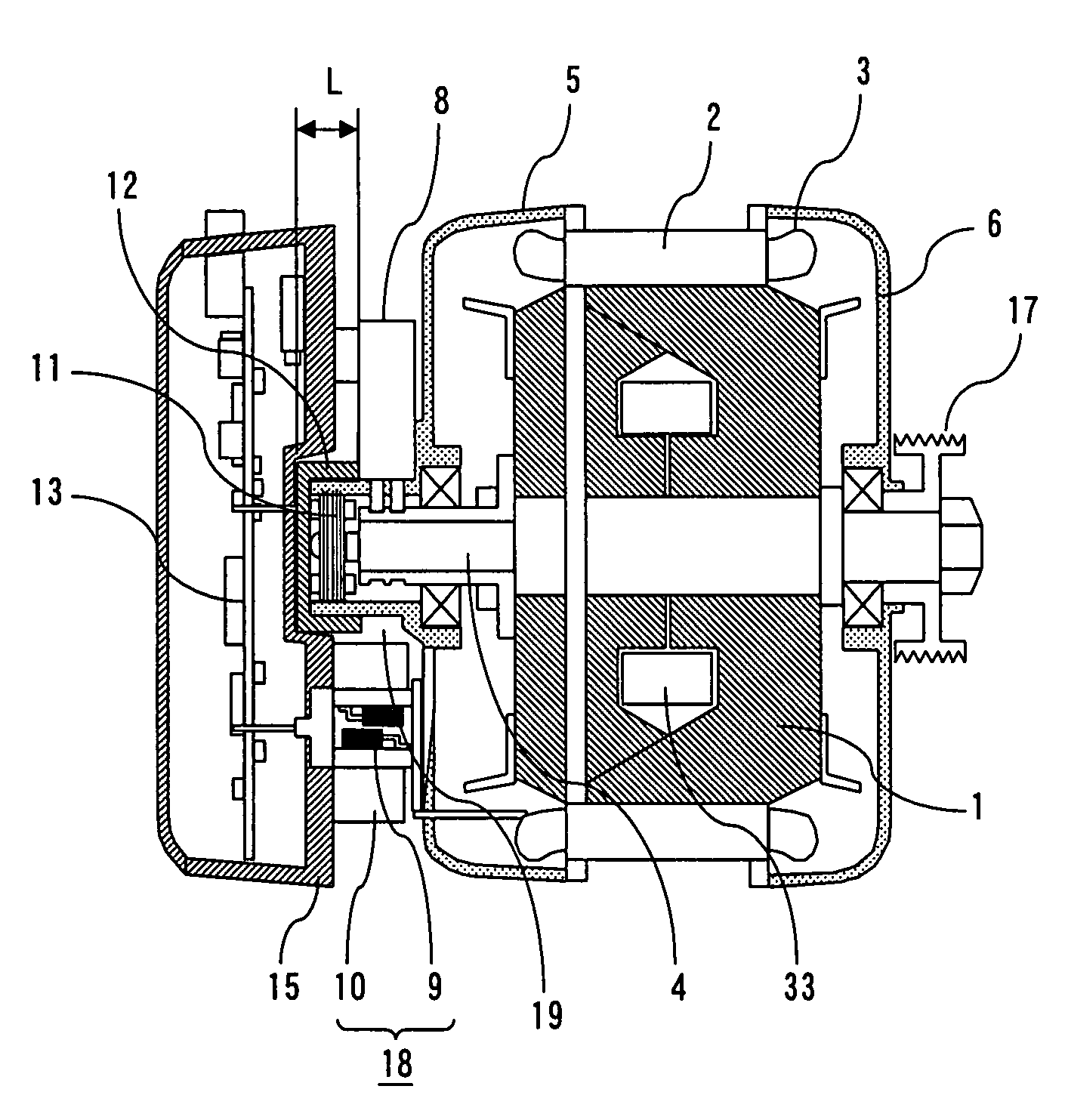
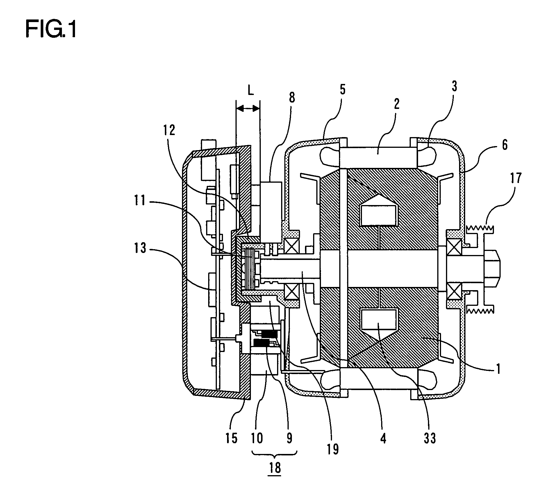
[0019]FIG. 1 is a sectional schematic view showing a first embodiment of an electric rotating machine according to the present invention, and FIG. 2 is a side view taken axially the peripheral portion of a rotational position detector. The electric rotating machine according to this first embodiment is provided with a stator 2 supported and fixed to brackets 5 and 6, and a rotor 1 that includes a rotary shaft 4 rotatably supported by the brackets 5 and 6, and that is rotated coaxially with the stator 2. The stator 2 includes a stator winding 3, and the rotor 1 includes a rotor winding 33. A pulley 17 is attached to the load side of the rotary shaft 4, and the pulley 17 is connected to loads not shown. A power part 18 including a switching element 9 and a heat sink 10 is attached to the bracket 5 on the side opposite to the load side. A control circuit part 13 that controls the switching element 9 of the power part 18 is contained in a case 15 attached to the outside (in an opposite ...

embodiment 2

[0030]FIG. 6 is a sectional schematic view showing a second embodiment of the electric rotating machine according to the present invention. Being different from the foregoing first embodiment, the rotational position detector 11 and the power part 18 are disposed spaced apart in an axial direction of the rotary shaft 4. When the power part 18 and the rotational position detector 11 are located axially spaced apart, since the magnetic field to be generated by the power part 18 is attenuated, noise can be reduced further.

[0031]Furthermore, in the case of a field winding-type AC electric rotating machine, since the brush 8 for carrying current through the rotor winding 33 is mounted so as to be in contact with a slip ring 32 of the rotary shaft 4, the shield member 12 cannot be disposed at the brush part 8. In this case, however, as shown in FIG. 6, by arranging the rotational position detector 11 with a shift in a direction opposite to the load side in an axial direction of the rotary...

examples

[0033]FIG. 7 shows results of comparing noise levels in output signals from the rotational position detector 11 in cases where the shield members 12 are constructed with different configurations and materials, and these shield members 12 of various constructions are used. The rotational position detector 11 according to the embodiments is made of a member such as a gear in which a winding is mounted onto a core of a magnetic substance. Further, the rotational position detector 11 is a resovler that is attached to the rotary shaft of the rotor and that detects rotational positions from voltage changes taking place at the winding mounted on the core due to magnetic changes caused by the rotation of the rotor.

[0034]With reference to FIG. 7, a conductor A is copper, a conductor B is aluminum, a magnetic substance A is soft magnetic ferrite, and a magnetic substance B is iron-based soft magnetic substance in which an insulating layer is formed on the surface of a thin plate.

[0035]Configu...


PUM


Abstract

An electric rotating machine comprises: a stator; a rotor that includes a rotary shaft, and rotates coaxially with the stator; a bracket supporting and fixing the stator, and supporting rotatably the rotary shaft; a rotational position detector disposed on the side opposite to the load of the rotary shaft to detect a rotational position of the rotor; and a power part including a switching element disposed on the outer circumferential side of the rotational position detector. A shield member is disposed at the rotational position detector to cover the circumference and shield a magnetic field generated by the switching element.

Description

BACKGROUND OF THE INVENTION[0001]1. Field of the Invention[0002]The present invention relates to an electric rotating machine such as motor and, more particularly, to a small-sized electric rotating machine that includes a rotational position detector and a switching element part controlling current flowing through the electric rotating machine, and that is suitably mounted occupying a small space such as for use in vehicles.[0003]2. Description of the Related Art[0004]In an electric motor integrated with a control device that is disclosed, for example, in the Japanese Patent Publication (unexamined) No. 27903 / 1999 (on pages 4-5, FIG. 2), a control device case is fixed to an end bracket or to a housing on the side opposite to the load of an electric motor, and a cooling fan is attached to an end portion on the side opposite to the load of a shaft running through the control device case. The control device case contains an inverter circuit and a positional detector of a rotor that is...

Claims


Application Information

Patent Timeline
Patent Type & Authority Patents(United States)
IPC IPC(8): H02K11/00
CPCH02K11/0005H02K11/0021H02K11/0073H02K11/046H02K11/215H02K11/33H02K11/0141H02K11/05
Inventor KIKUCHI, MASAOISODA, HITOSHI
Owner MITSUBISHI ELECTRIC CORP
Why Eureka
Try Eureka