Device for charging batteries

a battery and charging device technology, applied in the field of charging devices, can solve the problems of inability to recognize battery types at all, inability to identify magnetic elements of batteries in a way that might influence the components of handheld devices in an unwanted manner, and achieves simple circuit, good resistance to high temperatures, and extreme resistance to soiling.

Active Publication Date: 2010-12-07
ARTHREX
View PDF14 Cites 16 Cited by
  • Summary
  • Abstract
  • Description
  • Claims
  • Application Information

AI Technical Summary

Benefits of technology

[0008]With the inventive devices for charging batteries, hereinafter also referred to as chargers, the different types of batteries or accumulators are recognized by a proximity-type or contactless magnetic identification device. This advantageously eliminates the need for direct contact between the battery to be charged and the identification device and thus the risk of invalid identification due to impaired contacting. The inventive device and the inventive battery are extremely resistant to soiling, have a good resistance to high temperatures, such as the temperatures needed for sterilization of the battery, for example, and are characterized by a simple circuit; furthermore, they generate only a low radiant emission with respect to limit values that must be maintained with regard to electromagnetic compatibility (EMC requirements).
[0015]In a second preferred variant of the second exemplary embodiment, the magnetic sensor detects the presence of a magnetic field of the magnetic element as long as no battery is connected to the charger. The battery comprises a shielding device which deflects or shields the magnetic field from the magnetic sensor, so that after connecting the battery to the charger, the magnetic sensor detects that no magnetic field is present and emits an identification signal. This variant is advantageous, in particular in stepped contact devices, whereby one of the two elements is a sensor or magnet at the bottom of the step and the other of the two elements is arranged on the leg at an angle thereto. This makes it possible to achieve a particularly good shielding effect. In this variant, several magnetic elements and magnetic sensors may also be provided.
[0016]In one embodiment, the at least one magnetic parameter varying device comprises paramagnetic or preferably ferromagnetic material. This material concentrates or bundles the magnetic field lines, in particular in its surroundings, thus raising the magnetic field strength in the surroundings. To achieve this effect, preferably the magnetic conductivity of the at least one magnetic parameter varying device is higher then the magnetic conductivity of its surroundings. A magnetic sensor, which is in the vicinity of the magnetic parameter varying device, may detect the rising magnetic field strength and send a signal to identify the battery. The paramagnetic or ferromagnetic material may comprise, for example, platinum, lithium, sodium, potassium and iron, cobalt or nickel.
[0017]In one embodiment, the at least one magnetic parameter varying device comprises diamagnetic material. This material diverts the magnetic field lines, in particular in its surroundings, thus reducing the magnetic field strength in the surroundings. A magnetic sensor, which is in the vicinity of the magnetic parameter varying device, may detect the reduced magnetic field strength and send a signal to identify the battery. The diamagnetic material may comprise, for example, bismuth.
[0018]In another embodiment, the at least one magnetic parameter varying device is nonmagnetic, in other words it does not have a magnetic source, e.g. a permanent magnet. This embodiment has the advantage that the magnetic parameter varying device does not affect or interfere with elements of the battery or electronic parts of a device that the battery is intended to power, e.g. an electronic motor of a medical handpiece.

Problems solved by technology

All these identification devices have disadvantages, however; in particular due to the repeated use there may be changes in the mechanical components, so that invalid contact resistances occur in the resistance measurement, for example, and therefore the type of battery is not recognized at all or is identified incorrectly.
If a battery with a magnetic element is inserted into the handle, e.g., for driving the motor of the handheld device, there is the risk that the magnetic field of the magnetic element of the battery might influence components in the handheld device in an unwanted manner, in particular magnetic sensors present in the handheld device for control purposes.

Method used


Image

  • Device for charging batteries
  • Device for charging batteries
  • Device for charging batteries

Examples


Embodiment Construction

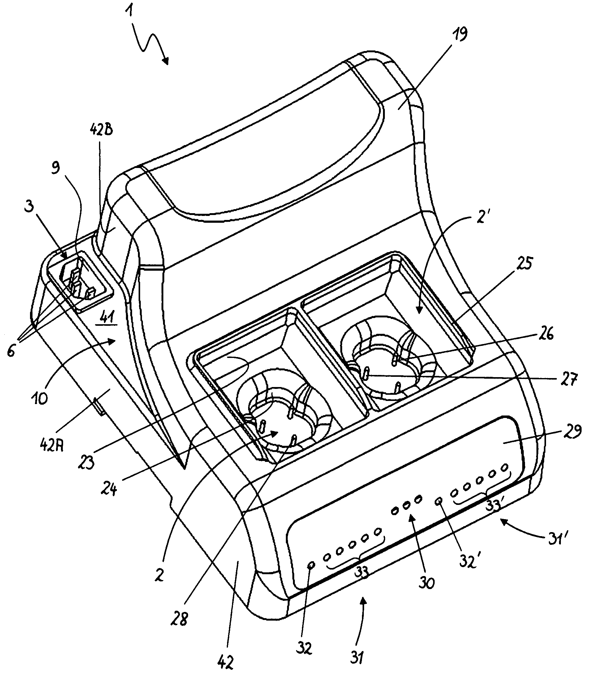
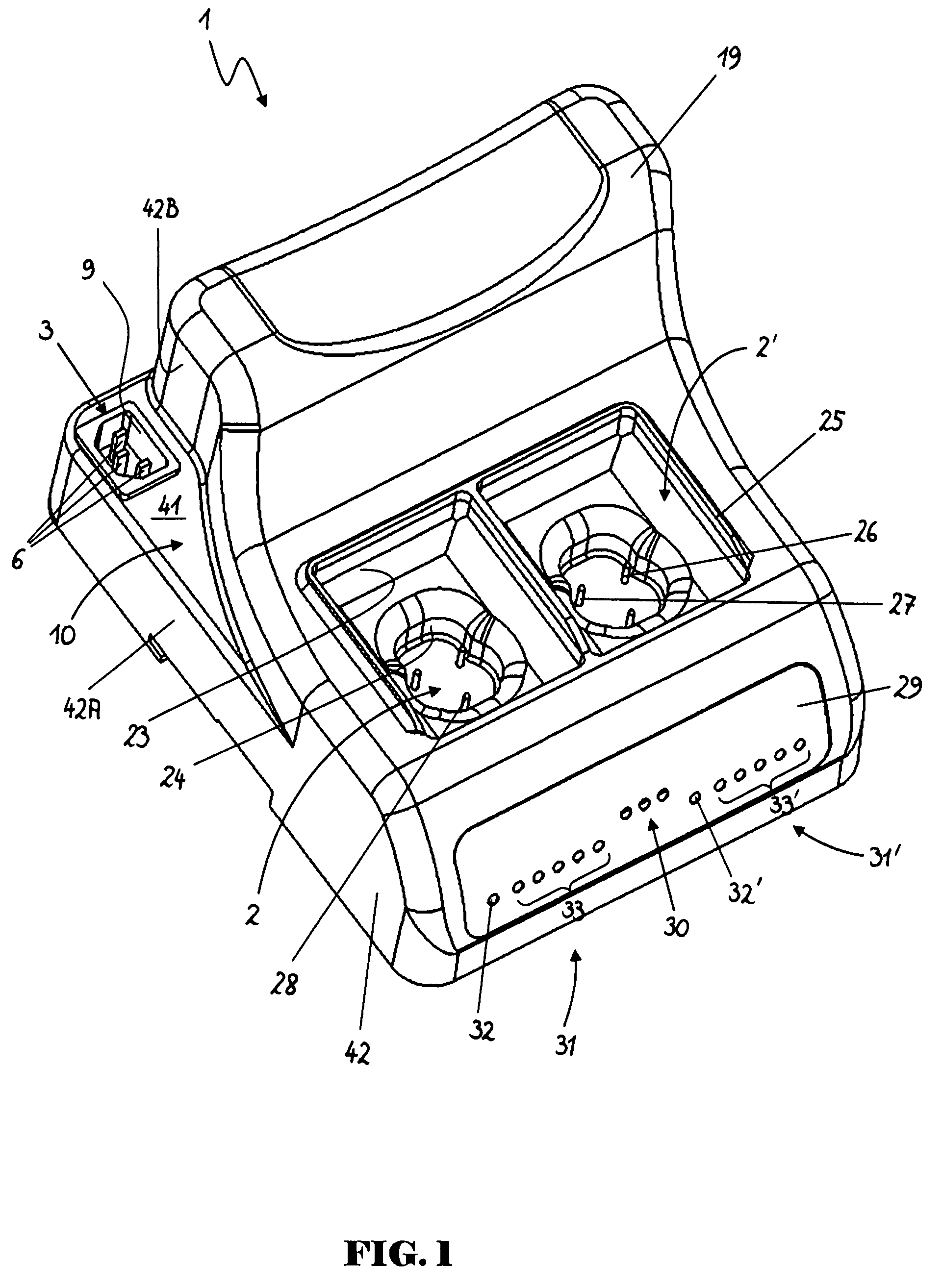
[0027]FIG. 1 shows a charger 1 having an outside housing 19 in which two electric contact devices 2, 2′ are arranged. The number of contact devices 2, 2′ is shown merely as an example, so the charger may of course also have only one or more than two contact devices. Each of the two contact devices 2, 2′ comprises a first recess 23 and a second recess 24, each in the form of an offset, which may have different diameters and shapes. Due to these different shapes, batteries with different outside shapes may be connected to the charger 1 and charged there. Recess 23 has essentially a rectangular shape, while recess 24 has a rounded, essentially oval shape. Recess 24 is arranged in recess 23 so that the contact devices 2, 2′ have a stepped design. A narrow web 25 surrounds three sides of each of the two contact devices 2, 2′.

[0028]FIG. 5 shows an example of a battery or an accumulator that can be charged with this charger 1. The battery 100 comprises a housing 95, which is preferably mad...


PUM

PropertyMeasurementUnit
distanceaaaaaaaaaa
distanceaaaaaaaaaa
distanceaaaaaaaaaa

Abstract

In a second preferred variant of the second exemplary embodiment, the magnetic sensor detects the presence of a magnetic field of the magnetic element as long as no battery is connected to the charger. The battery comprises a shielding device which deflects or shields the magnetic field from the magnetic sensor, so that after connecting the battery to the charger, the magnetic sensor detects that no magnetic field is present and emits an identification signal. This variant is advantageous, in particular in stepped contact devices, whereby one of the two elements is a sensor or magnet at the bottom of the step and the other of the two elements is arranged on the leg at an angle thereto. This makes it possible to achieve a particularly good shielding effect. In this variant, several magnetic elements and magnetic sensors may also be provided.

Description

CROSS REFERENCE TO RELATED APPLICATION[0001]The present application claims priority from pending European Patent Application No. 06020497.1, filed Sep. 29, 2006, which is incorporated herein by reference.BACKGROUND[0002]1. Field[0003]The present invention relates to devices for charging batteries and to batteries which can be charged with a charging device.[0004]2. Description of Prior Art[0005]Cordless medical handheld devices or handpieces having an internal power source in the form of batteries are becoming increasingly popular because of their ease of handling in comparison with handheld devices connected by a power cable to an external power source. Because of the different requirements, e.g., with respect to the power, design type or size of such cordless handheld devices, there is also a constantly proliferating number of batteries or types of batteries having different storage capacities, power supply, design, charging requirements, etc. To avoid requiring a separate charger...

Claims


Application Information

Patent Timeline
Patent Type & Authority Patents(United States)
IPC IPC(8): H02J7/00H01M50/209H01M50/284H01M50/296
CPCH01M2/1022H01M10/02H01M10/425H01M10/44H01M10/48H02J7/0009H01M10/4221H02J7/00043H02J7/00047Y02E60/10H01M50/209H01M50/284H01M50/296
Inventor SCHROECK, RAINERSTUERZER, CHRISTIAN
Owner ARTHREX
Why Eureka
Try Eureka