Axial bearing wear detection device for canned motor

a technology of axial bearings and wear detection devices, which is applied in the direction of instruments, structural/machine measurement, association with control/drive circuits, etc., can solve the problem that the internal conditions cannot be monitored visually, and achieve the effect of high precision

Inactive Publication Date: 2006-03-28
TEIKOKU ELECTRIC MFG
View PDF9 Cites 28 Cited by
  • Summary
  • Abstract
  • Description
  • Claims
  • Application Information

AI Technical Summary

Benefits of technology

[0026]With this arrangement, by means of the axial position detection circuit, the movement position in the axial direction of the rotor is detected from the difference in the voltages generated at the axial position detection coils disposed at the respective end parts in the axial direction of the stator. The voltage difference of the two axial position detection coils at the position detection circuit when the rotor is at a reference position in the axial direction is adjusted to zero by means of the axial zero point adjustment circuit that uses a voltage source, which varies in proportion to the power supply voltage of the canned motor, as a bias power supply. Even when the power supply voltage of the canned motor varies, the bias power supply of the axial zero point adjustment circuit varies in the same manner, and thus the zero point adjustment by the axial zero point adjustment circuit is not affected and axial bearing wear detection of high precision is enabled.

Problems solved by technology

Since a canned motor pump has a leak-less structure in which a canned motor and a pump are integrated, the internal conditions cannot be monitored visually.
The variation of the difference of the axial position detection coils Cf and Cr for the 0 mm axial position according to the magnitude of the power supply voltage is considered to be a cause of this problem.

Method used


Image

  • Axial bearing wear detection device for canned motor
  • Axial bearing wear detection device for canned motor
  • Axial bearing wear detection device for canned motor

Examples


Embodiment Construction

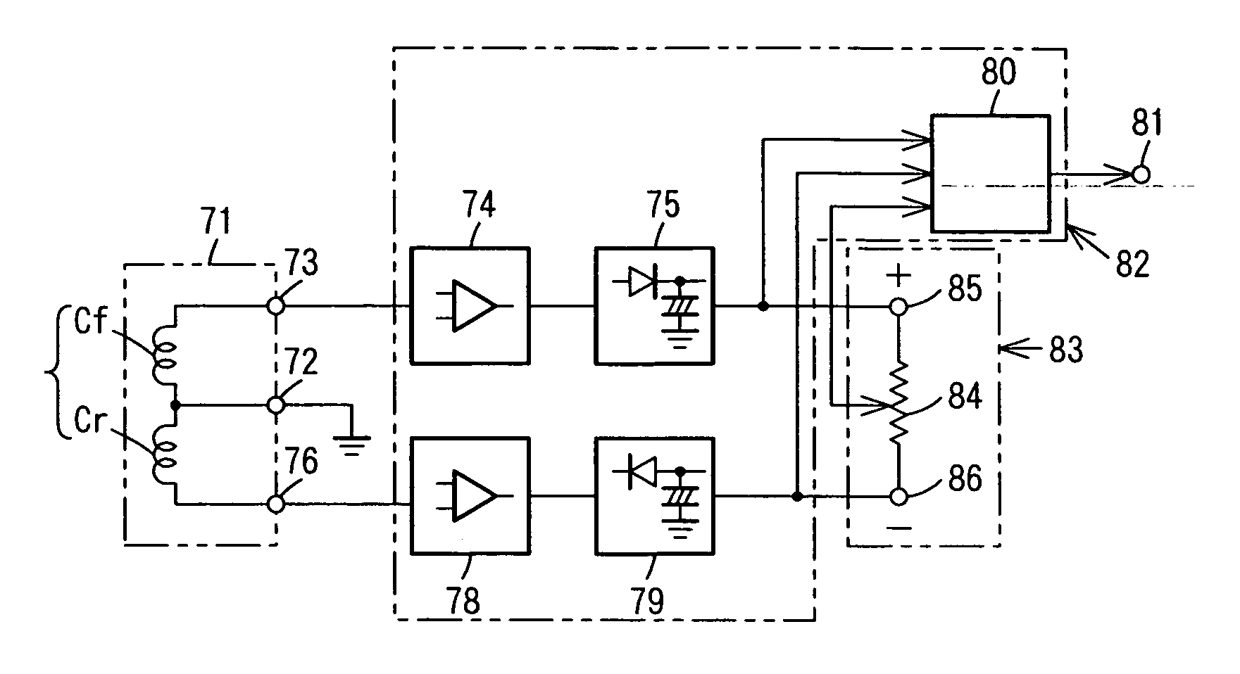
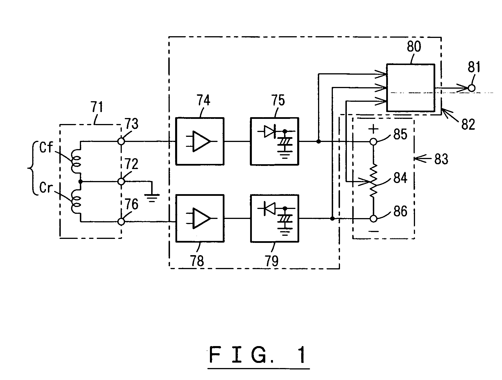
[0038]An embodiment of this invention shall now be described with reference to FIG. 1 through FIG. 5.

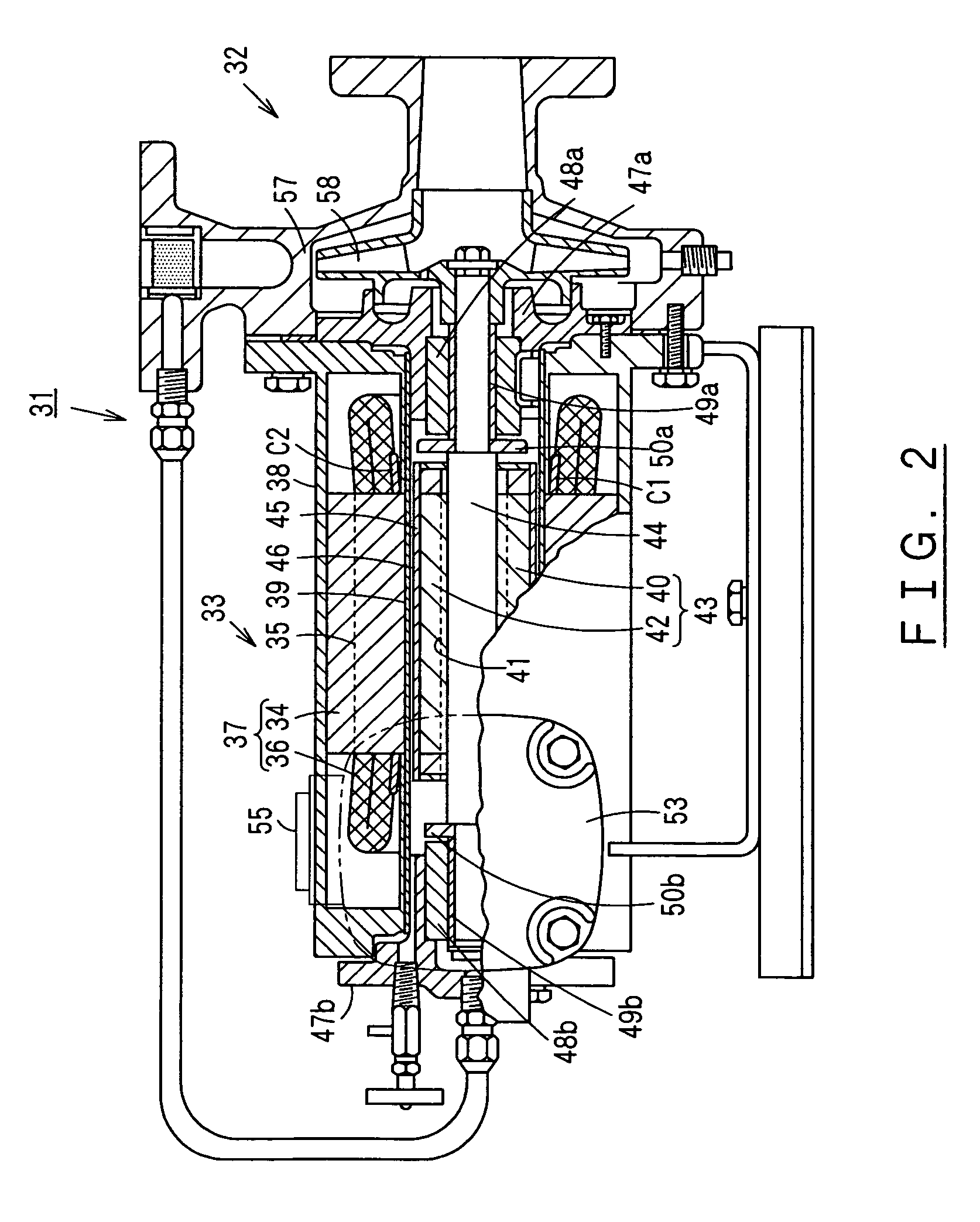
[0039]FIG. 2 is a partially cutaway front view of a canned motor pump to which an axial bearing wear detection device is applied. 31 is a canned motor pump, and with this canned motor pump 31, a pump 32 and a radial gap type canned motor 33 are joined integrally to each other in a fluid-tight manner.

[0040]In canned motor 33, a stator 37, arranged by winding stator winding 36 in stator grooves 35 of a stator iron core 34, is fitted inside a stator frame 38, a stator can 39, formed to a thin cylindrical shape from stainless steel or other non-magnetic material, is inserted in close contact to the inner peripheral surface of stator 37, and the respective end rims of stator can 39 are welded in a fluid-tight manner to stator frame 38. Also, a rotor shaft 44 is fitted into a rotor 43, arranged by attaching a rotor conductor 42 in rotor grooves 41 of a rotor iron core 40, and a rotor can 4...


PUM


Abstract

An axial position detection circuit detects the axial position of a rotor from the difference in voltages generated at axial position detection coils disposed at both ends in the axial direction of a stator of a canned motor. An axial zero point adjustment circuit uses a voltage supply, which varies proportionately with the power supply voltage of the canned motor, as a bias power supply to adjust the voltage difference of the axial position detection coils to zero when the rotor is at a reference position in the axial direction. Even if the power supply voltage of the canned motor varies, since the bias power supply of the axial zero point adjustment circuit varies in likewise manner, the zero point adjustment by the axial zero point adjustment circuit is not affected and axial bearing wear detection of high precision is enabled.

Description

CROSS-REFERENCE TO PRIOR APPLICATION[0001]This is a U.S. national phase application under 35 U.S.C. §371 of International Patent Application No. PCT / JP01 / 11082 filed Dec. 18, 2001 which is incorporated by reference herein. The International Application was published in Japanese on Jun. 26, 2003 as WO 03 / 052904 A1 under PCT Article 21(2).[0002]1. Technical Field[0003]This invention concerns an axial bearing wear detection device for detecting bearing wear in the axial direction of a canned motor.[0004]2. Background Art[0005]In general, a canned motor is mainly used for driving a pump and since it is used in a chemical plant, etc., it is required to be high in reliability.[0006]Since a canned motor pump has a leak-less structure in which a canned motor and a pump are integrated, the internal conditions cannot be monitored visually. In many cases, the canned motor's rotor, which rotatingly drives the pump's impeller, is supported by a slide bearing that is lubricated by the pump fluid,...

Claims


Application Information

Patent Timeline
Patent Type & Authority Patents(United States)
IPC IPC(8): G08B21/00H02K5/128H02K5/167H02K11/00
CPCH02K11/0078H02K11/0031H02K11/001H02K5/128H02K5/1672H02K11/20H02K11/225H02K11/35G01R31/34H02K11/00
Inventor MISATO, HISASHI
Owner TEIKOKU ELECTRIC MFG
Why Eureka
Try Eureka