
Joystick

Active Publication Date: 2006-03-28
MITSUMI ELECTRIC CO LTD
View PDF7 Cites 12 Cited by
  • Summary
  • Abstract
  • Description
  • Claims
  • Application Information

AI Technical Summary

Benefits of technology

[0008]It is therefore an object of the present invention to provide a rigid and durable joystick that prevents deformation of an arm, even if a user heavily operates the compact joystick.
[0015]In the above configuration, the lower arm is provided with bearing portions being opened at their lower faces which are formed by removing the lower faces of the center portions of both the side wall portions forming a long hole passed through the operating stick in almost semicircular shapes, respectively, and the shaft portions of the operation stick are abutted against and fitted into the bearing portions from a lower side, respectively. Thus, unlike the related example, the operation stick is not required to be fitted into the shaft hole perforated at the arm by utilizing the elasticity of the arm. Thus, it is possible to make the arm well rounded or fat.
[0018]In the above configurations, the arm is removed in its thickness by a size corresponding to the moving amount of the operation stick, that is, only for portions corresponding to the long hole provided at a longitudinal direction of the arm and the bearing portions being opened in their lower face for fitting the shaft portions therein. Thus, the arm becomes more rigid and the durability thereof is remarkably improved. Accordingly, the invention can attain quite remarkable effects.

Problems solved by technology

Thus, the arm deforms due to the load and so the durability of the joystick is remarkably degraded.

Method used


Image

  • Joystick
  • Joystick
  • Joystick

Examples


Embodiment Construction

[0030]The embodiment of the invention will be explained in detail with reference to FIGS. 1 to 6. In this respect, portions same as those of the related technique are explained for the convenience of explanation.

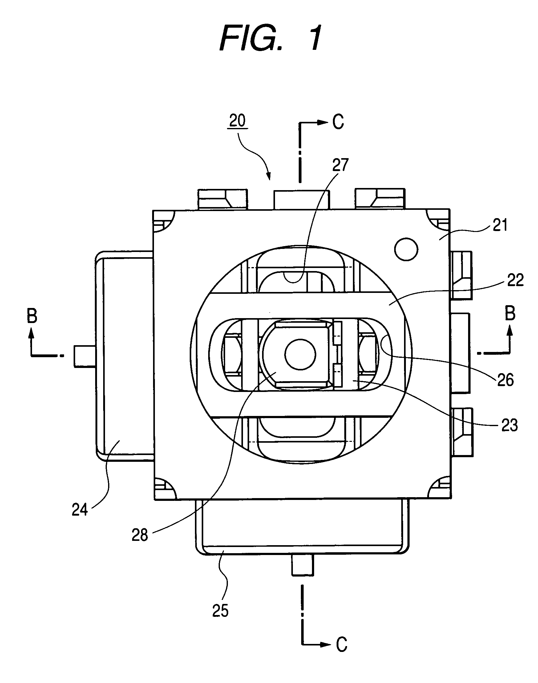
[0031]In FIG. 1, a reference numeral 20 depicts a joystick. The joystick 20 is configured in a manner that an upper arm 22 serving as an upper arm and a lower arm 23 being orthogonal to each other in the vertical direction are disposed so as to rotate freely within a casing 21. Each of the upper arm 22 and the lower arm 23 is pivotally supported at both end portions thereof by the casing 21. The one end portions of the upper arm 22 and the lower arm 23 are connected to variable resistors 24, 25, respectively.

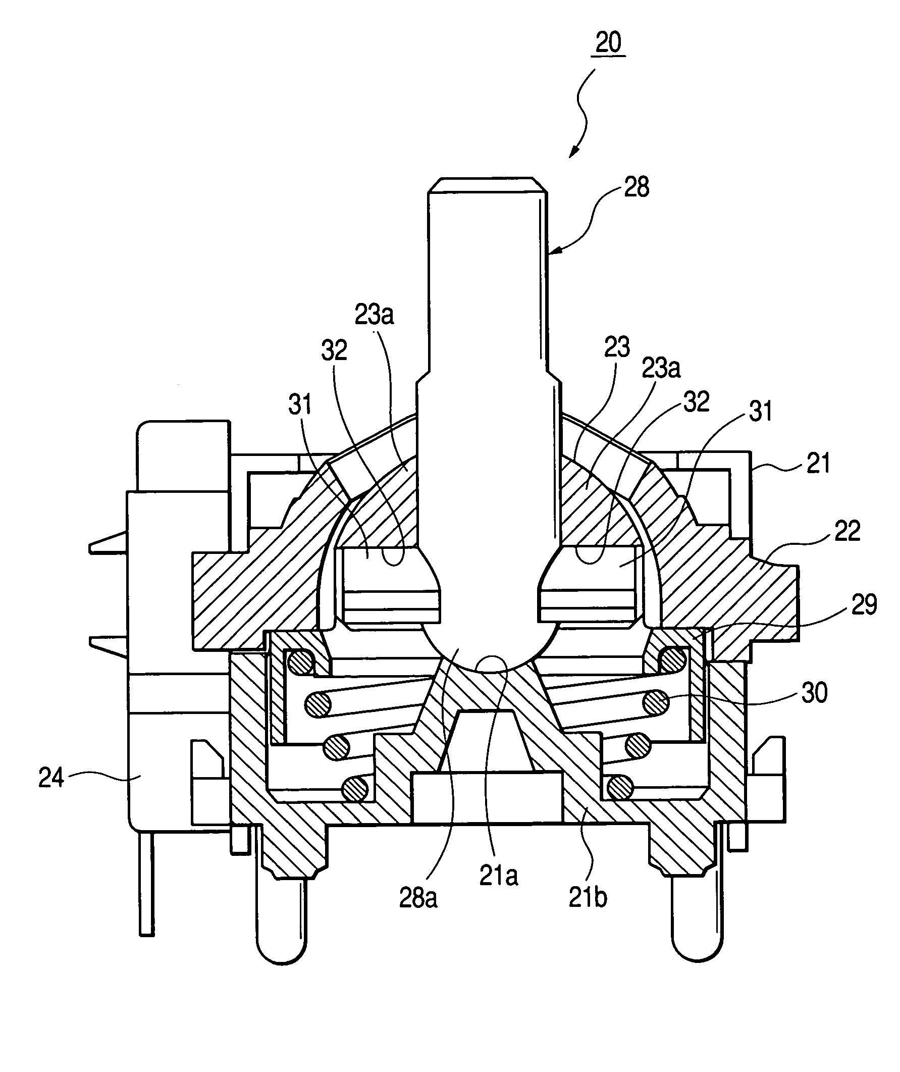
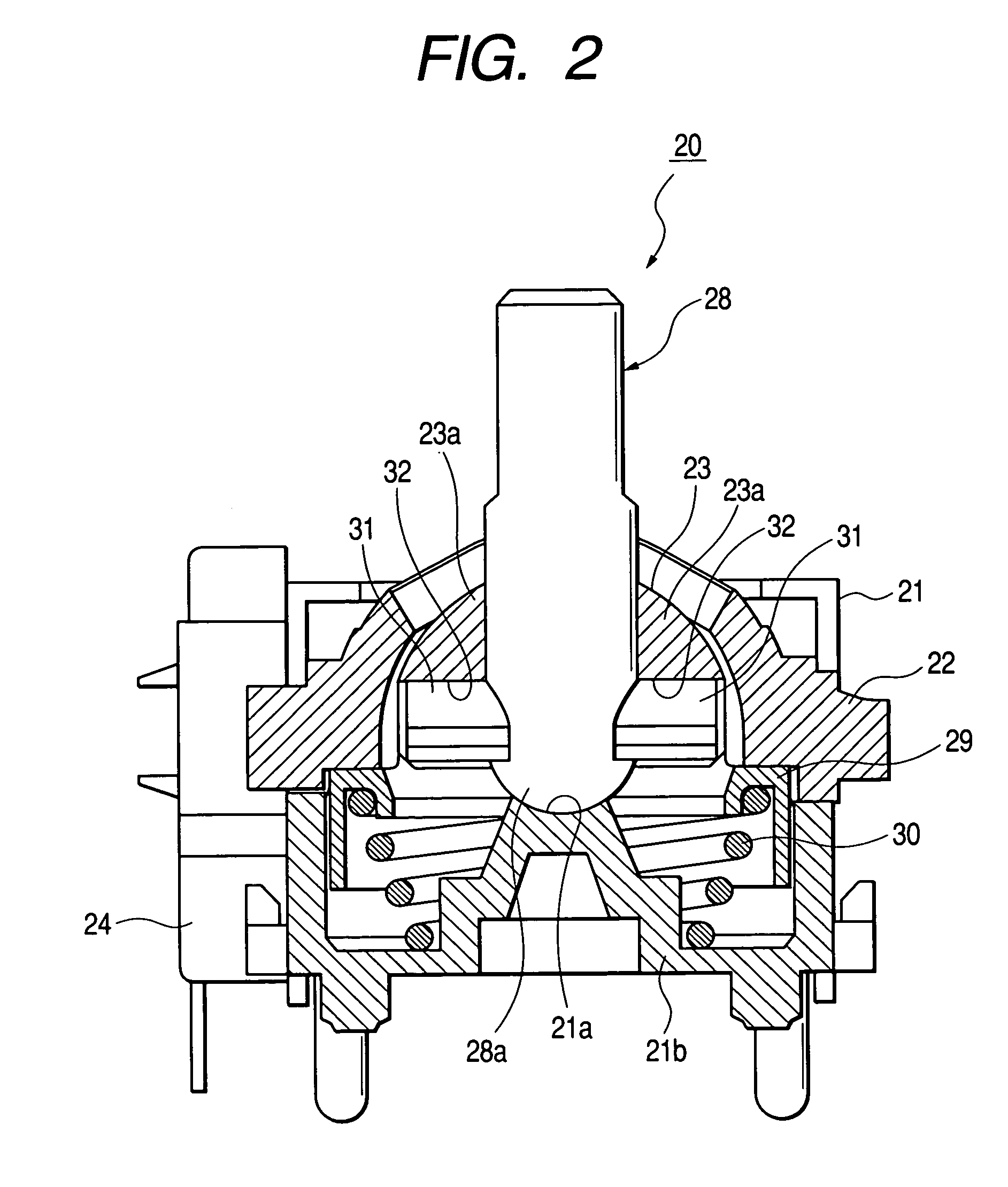
[0032]Long holes 26, 27 extending in the axial directions of the upper arm 22 and the lower arm 23 are opened at the center portions thereof, respectively. An operation stick 28 is provided so as to pass through the long holes 26, 27. The lower end portion of the operati...


PUM


Abstract

A joystick includes an operating stick having shaft portions protruded from a lower end thereof, an upper arm which supports the operating stick so as to be pivotable in a first direction, a lower arm which supports the operating stick so as to be pivotable in a second direction which is perpendicular to the first direction, and bearing portions which are formed at a lower face of the central portion of the lower arm for bearing the shaft portions. The bearing portions are concaved, and the shaft portions are fitted into the bearing portions from a lower side respectively.

Description

BACKGROUND OF THE INVENTION[0001]The present invention relates to a joystick and, in particular, relates to a compact joystick in which an arm member has a wall thickness suitable to strengthen and improve the durability thereof.[0002]Joysticks disclosed in the related prior art will be explained with reference to FIGS. 7 and 8. In the figures, a joystick 1 is configured in a manner that the arms 3 and 4 being orthogonal to each other in the vertical direction are disposed so as to rotate freely within a casing 2. Each of the arms 3 and 4 is pivotally supported at both end portions thereof by the casing 2. The one end portions of the arms 3 and 4 are connected to variable resistors 5, 6 serving as signal output units, respectively.[0003]Long holes 7, 8 extending in the longitudinal directions of the arms 3, 4 are opened at the center portions of the arms 3, 4, respectively. An operation stick 9 serving as an operation stick is provided so as to pass through the long holes 7, 8. The ...

Claims


Application Information

Patent Timeline
IPC IPC(8): G09G5/08G06F3/0338G05G9/047
CPCG05G9/047Y10T74/20201G05G2009/04733G05G2009/04703
Inventor FURUKAWA, HITOSHI
Owner MITSUMI ELECTRIC CO LTD
Features
  • Generate Ideas
  • Intellectual Property
  • Life Sciences
  • Materials
  • Tech Scout
  • Unparalleled Data Quality
  • Higher Quality Content
  • 60% Fewer Hallucinations
Learn More