Head positioning method, and disk apparatus using the same

a positioning method and head technology, applied in the field of head, can solve the problems of reducing data format efficiency, unstable positioning system, further deteriorating the positioning precision of the magnetic head, etc., and achieve the effect of suppressing off-track due to disturbance, increasing the control frequency of the head positioning system, and reducing the efficiency of data forma

Inactive Publication Date: 2006-03-28
PANASONIC CORP
View PDF11 Cites 21 Cited by
  • Summary
  • Abstract
  • Description
  • Claims
  • Application Information

AI Technical Summary

Benefits of technology

[0033]As described above, according to the present invention, the positioning of the head can be carried out using the general adjustment actuator and the fine adjustment actuator even at the time when the servo information is not sampled. By employing the method or structure of the present invention, it is possible to generate the position error signal independently of the sampling cycle of the servo information. Thus, it is possible to increase the control frequency of the head positioning system without increasing the number of servo sectors, i.e., without decreasing the data format efficiency.
[0034]At the same time when the head position estimation signal is generated, disturbance (such as the friction in the rotational bearing, the elastic force of the flexible print circuit, the impact or vibration on the disk apparatus, etc.) is estimated to compensate for the disturbance, whereby off-track due to disturbance is suppressed. As a result, the positioning of the head is stably and precisely carried out, and a highly reliable disk apparatus is provided.

Problems solved by technology

In such a case, if the control frequency is increased for the purpose of increasing the positioning precision, the positioning system may become unstable due to the natural vibration.
On the other hand, as the size of magnetic disk apparatuses has been decreased in recent years, disturbance such as the friction force in a rotational bearing supporting a head supporting mechanism or the elastic force of the flexible print circuit that connects the actuator with a circuit substrate, presents a factor that further deteriorates the positioning precision for the magnetic head.
However, as more servo information are recorded, the user data area is accordingly decreased, resulting in a decrease in the data format efficiency.
Thus, the ratio of the servo areas 110 to the total disk area increases as the disk size is decreased, resulting in a decrease in the data format efficiency.
Since this positioning method depends on the servo information, the band in which the disturbance can be estimated is limited by the sampling cycle of the servo information.
As a result, the external force is not appropriately compensated for.

Method used


Image

  • Head positioning method, and disk apparatus using the same
  • Head positioning method, and disk apparatus using the same
  • Head positioning method, and disk apparatus using the same

Examples


Embodiment Construction

[0046]Hereinafter, an embodiment of the present invention is described in detail with reference to the drawings.

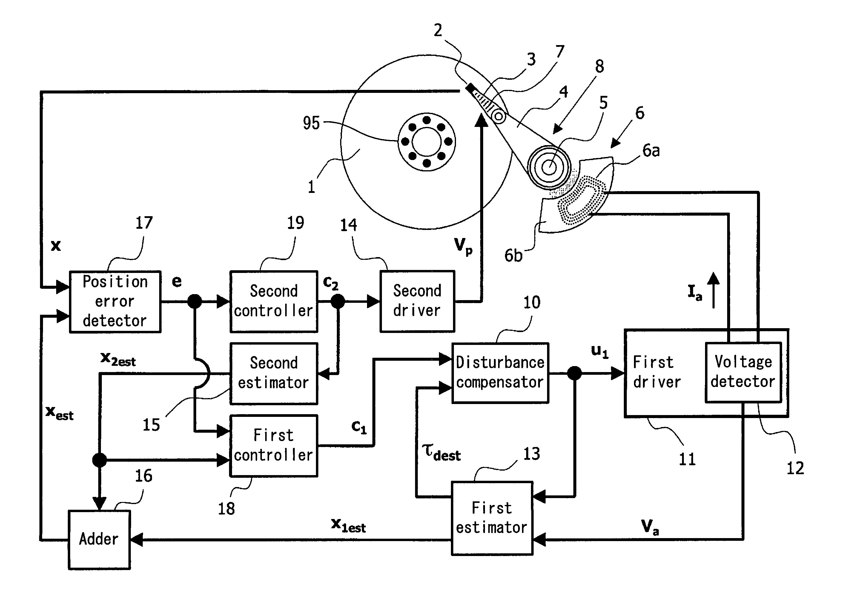
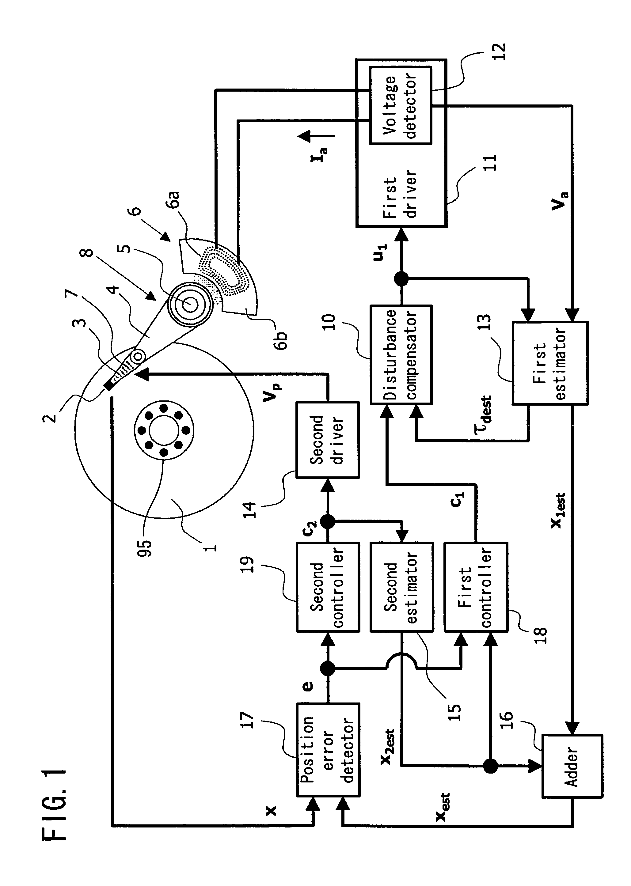
[0047]FIG. 1 is a block diagram showing the structure of a principal part of a magnetic disk apparatus according to an embodiment of the present invention. Referring to FIG. 1, a magnetic disk 1 is spun by a spindle motor 95. A slider 2 has a magnetic head 2a (see FIG. 6) mounted thereon, which records / reproduces data to / from the magnetic disk 1. The slider 2 is supported at an end of a suspension arm 3. The other end of the suspension arm 3 is supported at an end of a carriage 4. The carriage 4 is rotatably supported by a rotational bearing 5 which is fixed to a housing (not shown) of the magnetic disk apparatus.

[0048]Referring to FIG. 6, a fine adjustment actuator 7 which is formed by two thin film piezoelectric elements 7a and 7b is mounted on the suspension arm 3. The suspension arm 3 is structured such that the voltages applied to the thin film piezoelectric elements ...


PUM

PropertyMeasurementUnit
voltageaaaaaaaaaa
displacementaaaaaaaaaa
sizeaaaaaaaaaa

Abstract

A first estimator 13 estimates the position of a head based on a VCM driving signal u1 and a voltage signal Va output from a VCM 6 to output a first head position estimation signal x1est. The first estimator 13 estimates the disturbance acting on a head supporting mechanism 8 to output a disturbance estimation signal τdest. A second estimator 15 estimates the displacement of the head based on a control signal c2 for a fine adjustment actuator 7 to output a displacement estimation signal x2est. The first head position estimation signal x1est and the displacement estimation signal x2est are added together to obtain a second head position estimation signal xest. A position error signal e is generated using a head position signal x obtained by detecting the servo information and the second head position estimation signal xest. A disturbance compensator 10 synthesizes a VCM control signal c1 with the disturbance estimation signal τdest to generate the VCM driving signal u1.

Description

BACKGROUND OF THE INVENTION[0001]1. Field of the Invention[0002]The present invention relates to a positioning method for positioning a head, such as a magnetic head, an optical pickup, or the like, on a desired position of a target track of a disk (recording medium) with high precision by using a general adjustment actuator and a fine adjustment actuator. The present invention further relates to a disk apparatus using such a control method.[0003]2. Description of the Prior Art[0004]In recent years, disk apparatuses, such as magnetic disk apparatuses, and the like, have been improved rapidly by decreasing the size and increasing the capacity thereof. For example, the capacity of a magnetic disk apparatus has been increased by increasing the track density of the magnetic disk, and the track pitch will be further reduced in the future. Therefore, in order to record / reproduce data to / from a magnetic disk, it is necessary to precisely position a magnetic head on concentrical tracks form...

Claims


Application Information

Patent Timeline
Patent Type & Authority Patents(United States)
IPC IPC(8): G11B5/596G11B5/55G11B21/08
CPCG11B21/083G11B5/5552
Inventor MIYATA, KEIZOINAJI, TOSHIOKOHSO, HIROSHI
Owner PANASONIC CORP
Why Eureka
Try Eureka