
Receptacle device having circuit interrupting and reverse wiring protection

Inactive Publication Date: 2006-03-28
SHANGHAI MEIHAO ELECTRIC APPLIANCES
View PDF10 Cites 92 Cited by
  • Summary
  • Abstract
  • Description
  • Claims
  • Application Information

AI Technical Summary

Benefits of technology

[0019]According to another embodiment, the circuit interrupting device comprises a first conductor and a second conductor. A first pair of contacts is provided with each contact coupled to one of the first and second conductors. A second pair of contacts is moveable to a closed position via a reset button. A plunger is disposed in a solenoid. The plunger is moveable between a first position and second position when the solenoid is energized and de-energized, respectively. A current controller is coupled to the solenoid and to at least one of the first and second conductors via the second pair of contacts. The current controller prevents current flow

Problems solved by technology

However, most receptacles in homes are ordinary receptacles without the capability to protect against leakage of electric current.
When these ordinary receptacles are used, leakage of electric current or a shock hazard may occur.
However, until recently, most of these receptacles did not possess a reverse wiring protection feature.
When this occurs, although the input end and the output end of the receptacle are still electrically connected, the receptacle no long provides fault-protection.
Without a reverse wiring protection feature, a consumer, after mistakenly reversing the line wire and load wire connections to the receptacle may be misled to believe that the receptacle is still functioning properly and will detect a fault condition.
However, the consumer does not know that the fault-protection feature is not operational.
The continued use of a reverse wired receptacle might cause injury to users and damage to the household electronic appliances, as well as damage to real property.

Method used


Image

  • Receptacle device having circuit interrupting and reverse wiring protection
  • Receptacle device having circuit interrupting and reverse wiring protection
  • Receptacle device having circuit interrupting and reverse wiring protection

Examples


Embodiment Construction

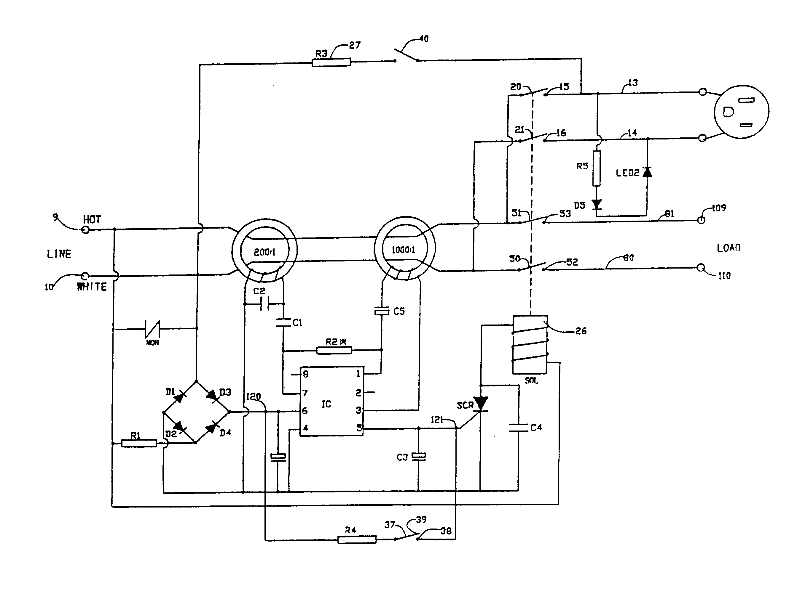
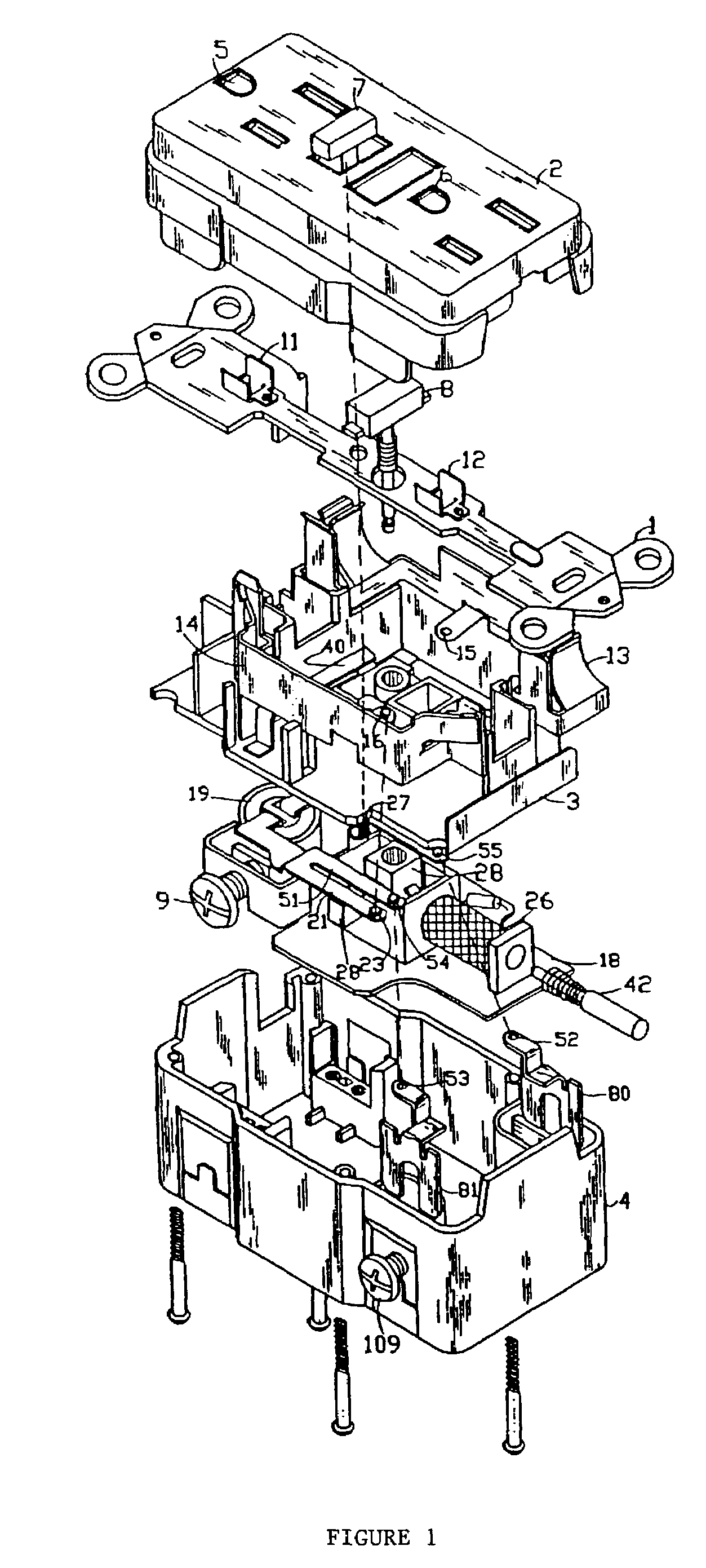
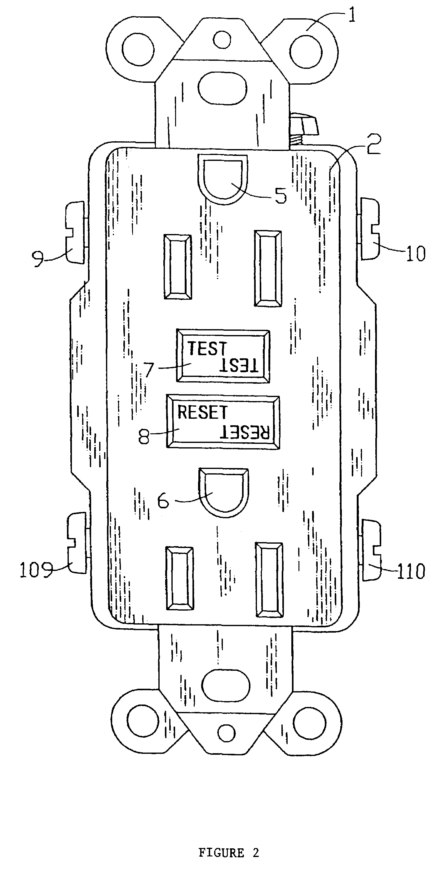
[0031]As shown in FIGS. 1–4, a circuit interrupting device, for example a GFCI, an AFCI, or other device, according to an exemplary embodiment of the present invention mainly comprises an upper cover 2, an intermediate support3, and a base 4 assembled together. As shown in FIG. 2, on the upper cover 2, there are two electric output plugs 5 and 6, a test button (TEST) 7, and a reset button (RESET) 8.

[0032]A mounting strap 1 is installed between the upper cover 2 and the intermediate support 3. The mounting strap 1 has ground points 11, 12 that are connected to ground receptacles of the electric output plugs 5, 6 through openings in the upper cover 2. An electric circuit board 18 is installed between the intermediate support 3 and the base 4.

[0033]As shown in FIG. 3, the intermediate support 3 includes a pair of output conductors 13, 14 that are made from conductive materials. The output conductors 13, 14 are disposed on either side of the support 3. The two output conductors 13 and 1...


PUM


Abstract

A circuit interrupting system has an upper cover, an intermediate support, and a base. A mounting strap is installed between the upper cover and the intermediate support, and a electric circuit board installed between the intermediate support and the base. The upper cover includes an electric output plug, a test button, and a reset button. The mounting strap includes a ground point that is connected to a ground receptacle of the electric output plug; the intermediate support on both sides a pair of output conductors. The electric circuit board comprises a differential transformer, a solenoid coil having a plunger inside, a reset button bias member, and a flexible switch; both sides of the base respectively comprise in parallel a pair of electric input connection screws and a pair of electric output point. The ground fault circuit interrupting system is installed within an output box on the wall of an ordinary household which prevents hazard caused to human and household electronics by errors in the installation of the connection lines.

Description

RELATED APPLICATION[0001]This application claims the priority of Chinese Patent Application No. 02243497.6, filed on Aug. 7, 2002, which is incorporated herein by reference.FIELD OF THE INVENTION[0002]The present invention relates to a receptacle device, particularly a ground fault circuit interrupter (GFCI) or an arc fault circuit interrupter (AFCI), which provides protection to humans and property against faults in electrical equipment and in electrical supply and distribution systems so that upon detection of a fault condition, the receptacle device interrupts the electric supply circuit. The receptacle device is also capable of protecting against faults caused by reverse wiring.BACKGROUND OF THE INVENTION[0003]Safety associated with the use of household appliances is a great concern for people. This is especially the case as more and more electronic devices are used in homes today. Accordingly, it is desired to provide the electric receptacles in the walls of ordinary households...

Claims


Application Information

Patent Timeline
IPC IPC(8): H02H3/16H01H83/04H01R13/713H02H1/00
CPCH01H83/04H02H1/0015H01R13/7135H01H2083/201
Inventor HUANG, HUADAOLI, CHENGLI
Owner SHANGHAI MEIHAO ELECTRIC APPLIANCES
Learn More