Switching-type power converter

a power converter and switch-type technology, applied in the direction of power conversion systems, dc-dc conversion, climate sustainability, etc., can solve the problems of switching loss, non-zero voltage, and techniques with drawbacks

Active Publication Date: 2006-03-28
FUNG SZE WEI +1
View PDF3 Cites 59 Cited by
  • Summary
  • Abstract
  • Description
  • Claims
  • Application Information

AI Technical Summary

Problems solved by technology

This switching loss results from the overlapping of non-zero voltage and current waveforms during the switching transient.
But these techniques have some drawbacks.
And when the switching transient becomes very fast, the current slope (di / dt) and voltage slope (dv / dt) will become very large and may cause serious noise problems.
In practice, the zero-voltage switching method is not completely satisfactory in commercial power conversion products.
In order to perform the zero-voltage switching function, a special IC or many more components are usually required, thereby increasing the size and production cost of the power converter.
In practice, in order to design a resonant path, some bulky passive components are used (such as a large choke) that increase the size and conduction loss of the converter.
Because of the complexity of the resonant circuit and the control loop, tedious calculations and computer simulations are usually needed.
This complicates product design and production.
When operated outside of its narrow loading range, it enters the hard-switching mode that greatly increases the heat loss.
In general, designing a reliable zero-voltage switching circuit that can cover a wide loading range is very difficult.

Method used


Image

  • Switching-type power converter
  • Switching-type power converter
  • Switching-type power converter

Examples


Embodiment Construction

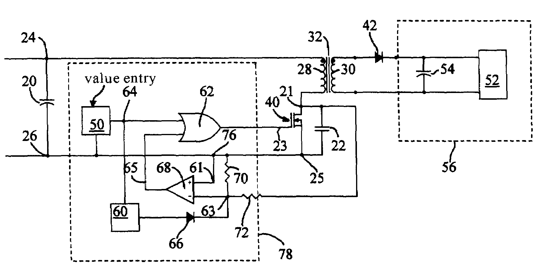
[0025]The preferred embodiment of the invention consists of (1) loading-independent zero-voltage switching (LIZVS) circuit, (2) pulse width extension tracking (PWET) circuit, and (3) current ripple cancellation (CRC) circuit.

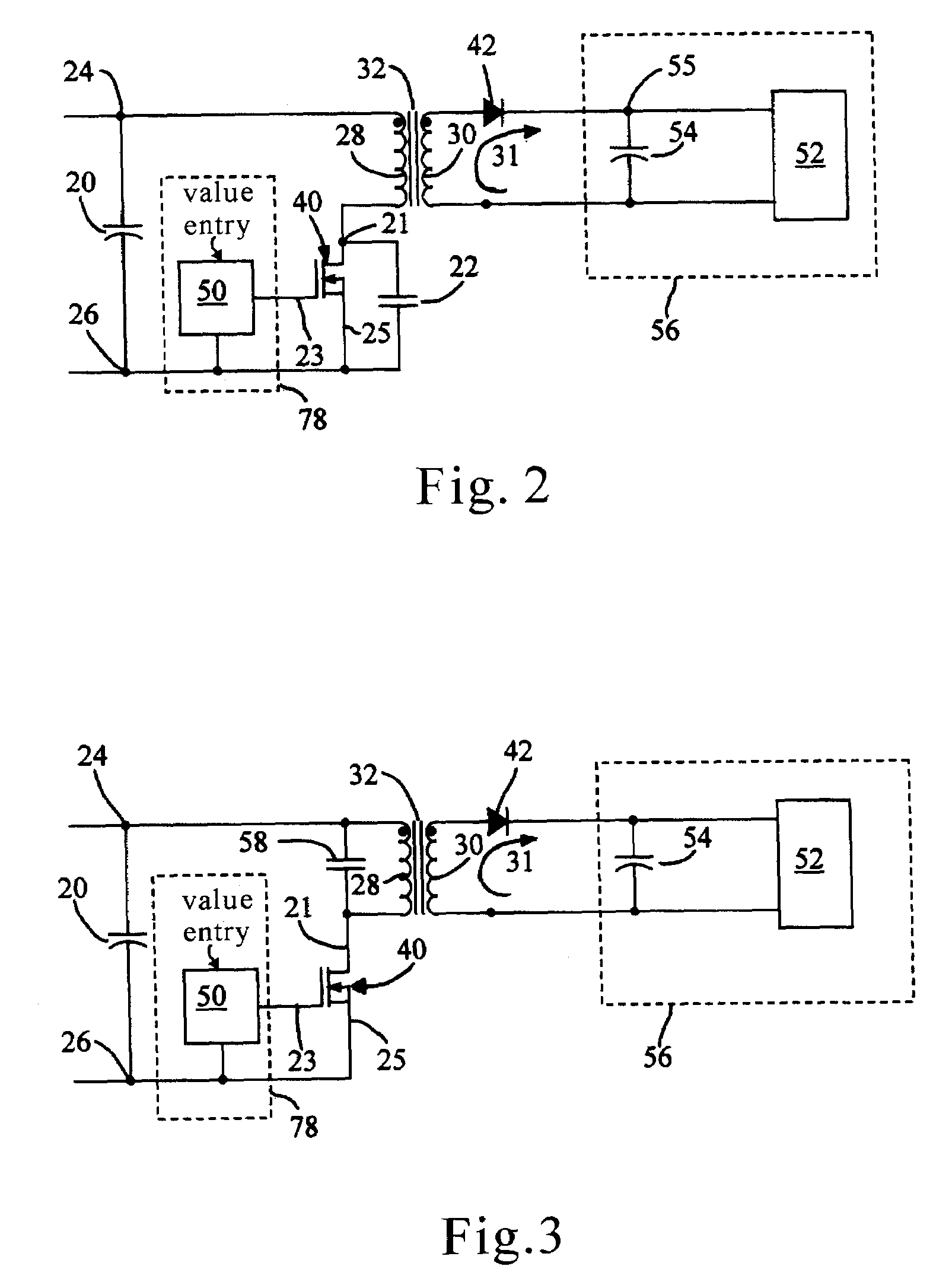
[0026]The LIZVS circuit is shown in FIG. 2. Zero-voltage switching is used to reduce the switching loss. The resonant elements are primary winding 28 of transformer 32 and capacitor 22. The capacitor can be connected alternatively across transformer primary winding 28 as shown in FIG. 3.

[0027]In order to make the resonant characteristic independent of the loading current, current flow through transformer secondary winding 31 is blocked by the reverse biasing of diode 42 when the primary winding 28 and capacitor 22 resonate. Consequently, there is no secondary current to affect the inductance of primary winding 28.

[0028]Input nodes 24 and 26 (reference) connect to input capacitor 20. Pulse generator 50 drives switch 40. When switch 40 turns on, current flows thro...


PUM


Abstract

An apparatus for increasing efficiency and reducing heat dissipation in power converters is disclosed. Zero-voltage-switching (ZVS) can reduce switching loss of power converters but it often results in a very complicated design and only works well under constant output current. In order to allow the ZVS to work over a wide loading range, the transformer secondary current is blocked when the primary starts to resonate. Hence, the resonant voltage waveform across the switch will not change even when the loading current is changing. Such a resonant voltage waveform is obtained with the aid of the transformer primary inductance and capacitor(s). Also provided is a novel driving circuit which controls the switching. Alternatives and variations of this apparatus can be made to satisfy different applications such as power conversion and power inversion. The subject power converter significantly lowers the heat loss and achieves higher efficiency for very wide loading ranges.

Description

BACKGROUND OF INVENTION[0001]This invention relates to switching-type power converters and in particular to the reduction of power loss and heat dissipation of such converters over a wide load range of operation.[0002]Power converters can be divided into linear type and switching type. The switching converter has the great advantages of light weight, small size and greater efficiency compared with the linear converter.[0003]A typical dc-dc switching converter circuit such as the one shown in FIG. 1 receives input power from input terminals 24, 26 and produces a switching waveform across the primary winding 28 of transformer 32. The electric power entering primary winding 28 is coupled to secondary winding 30 which feeds the power to a rectifying circuit which in turn outputs converted power to load 38.[0004]The basic forward converter topology shown in FIG. 1 is probably the most widely used topology for powers under 300 W. Input capacitor 20 compensates for the inductance of the ca...

Claims


Application Information

Patent Timeline
Patent Type & Authority Patents(United States)
IPC IPC(8): H02M3/335H02M3/337
CPCH02M3/33538H02M3/3378Y02B70/1433Y02B70/10
Inventor FUNG, SZE WEIFUNG, HUI SHUN
Owner FUNG SZE WEI
Why Eureka
Try Eureka