Methods for evaluating and improving drilling operations

a drilling operation and drilling tool technology, applied in the field of conventional drilling systems, can solve the problems of affecting the affecting the drilling performance of drilling tool assemblies, so as to and improve the drilling performance parameter

Inactive Publication Date: 2006-03-28
SMITH INT INC
View PDF17 Cites 107 Cited by
  • Summary
  • Abstract
  • Description
  • Claims
  • Application Information

AI Technical Summary

Benefits of technology

[0019]In one aspect, the present invention relates to a method for improving drilling performance of a drilling tool assembly. The method includes performing a drilling simulation to simulate an original drilling operation. The drilling simulation includes simulating an effect on the drilling tool assembly of an interaction of a cutting element of a drill bit with an earth formation. A solution to improve a drilling performance parameter is defined based upon the drilling simulation.

Problems solved by technology

However, in most cases, the majority of the fluctuation in the WOB can be attributed to drilling tool assembly vibrations.
Drilling tool assembly vibrations may also result from vibration of the drill bit during drilling.
In general, drilling tool assemblies may experience torsional, axial, and lateral vibrations.
Although partial damping of vibration may result due to viscosity of drilling fluid, friction of the drill pipe rubbing against the wall of the well bore, energy absorbed in drilling the formation, and drilling tool assembly impacting with well bore wall, these sources of damping are typically not enough to suppress vibrations completely.
Vibrations of a drilling tool assembly are difficult to predict because different forces may combine to produce the various modes of vibration, and models for simulating the response of an entire drilling tool assembly including a drill bit interacting with formation in a drilling environment have not been available.
Drilling tool assembly vibrations are generally undesirable, not only because they are difficult to predict, but also because the vibrations can significantly affect the instantaneous force applied on the drill bit.
This can result in the drill bit not operating as expected.
For example, vibrations can result in off-centered drilling, slower rates of penetration, excessive wear of the cutting elements, or premature failure of the cutting elements and the drill bit.
Lateral vibration of the drilling tool assembly may be a result of radial force imbalances, mass imbalance, and drill bit / formation interaction, among other things.
Lateral vibration results in poor drilling tool assembly performance, overgage hole drilling, out-of-round, or “lobed” well bores and premature failure of both the cutting elements and drill bit bearings.
Because the length of a drilling tool assembly may extend for more than a mile, pipe trips can take several hours and can pose a significant expense to the well bore operator and drilling budget.
While prior art simulation methods, such as those described above provide a general means for predicting drilling tool assembly dynamics, simulation techniques have not been developed to cover actual drilling with a drilling tool assembly in a well bore including a complete simulation of the drill string, the BHA, and the drill bit that takes into account the interaction of the cutting elements on the drill bit with the earth formation being drilled.
As a result, accurately modeling and predicting the response of a drilling tool assembly during drilling has been virtually impossible.
Additionally, the change in the dynamic response of a drilling tool assembly while drilling when a component of the drilling tool assembly is changed has not been well understood.
Such iterative design and selection methods are time consuming and can be costly for drilling operations.
In particular, replacement of a poorly performing drill bit or failure of another component of a drilling tool assembly requires the time and expense of removing the drilling tool assembly from the well bore, which may take many hours depending on the depth of the well.

Method used


Image

  • Methods for evaluating and improving drilling operations
  • Methods for evaluating and improving drilling operations
  • Methods for evaluating and improving drilling operations

Examples


Embodiment Construction

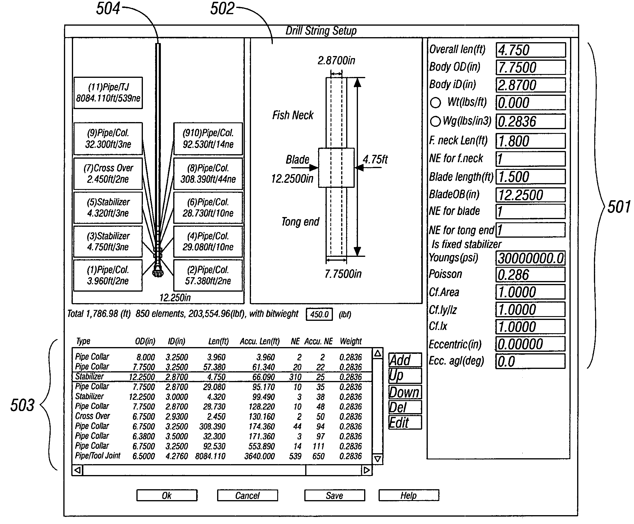
[0045]In one aspect, the present invention provides a method for evaluating drilling information to provide a solution to improve drilling performance. In one embodiment, the method includes obtaining drilling information and evaluating the drilling information to determine the performance of an actual drilling tool assembly in drilling earth formation or to establish the expected performance of a proposed drilling tool assembly in drilling earth formation. The method may further include utilizing the evaluation and / or the determined performance of the drilling tool assembly to define at least one potential solution to improve the drilling performance of the actual or proposed drilling tool assembly. A solution may involve any combination of adjustments to the drilling tool assembly design parameters or the operating parameters used for drilling with the drilling tool assembly.

[0046]In another aspect, the present invention provides a method for improving the drilling performance of ...


PUM


Abstract

A method for improving drilling performance of a drilling tool assembly is disclosed. The method includes identifying a drilling performance parameter to be improved. One or more potential solutions are defined to improve the drilling performance parameter. A drilling simulation is performed to determine the dynamic response of the drilling tool assembly during a drilling operation. Determining the dynamic response includes determining the interaction of a cutting element of a drill bit with an earth formation. Improvement in the drilling performance parameter is determined based upon the drilling simulation.

Description

CROSS-REFERENCE TO RELATED APPLICATIONS[0001]This application is a continuation-in-part of U.S. Pat. No. 6,785,641, issued on Aug. 31, 2004, and claims the benefit, pursuant to 35 U.S.C. §120, of that patent. That patent is incorporated by reference in its entirety.BACKGROUND OF THE INVENTION[0002]FIG. 1 shows one example of a conventional drilling system for drilling an earth formation. The drilling system includes a drilling rig 10 used to turn a drilling tool assembly 12 that extends downward into a well bore 14. The drilling tool assembly 12 includes a drilling string 16, and a bottomhole assembly (BHA) 18, which is attached to the distal end of the drill string 16. The “distal end” of the drill string is the end furthest from the drilling rig.[0003]The drill string 16 includes several joints of drill pipe 16a connected end to end through tool joints 16b. The drill string 16 is used to transmit drilling fluid (through its hollow core) and to transmit rotational power from the dr...

Claims


Application Information

Patent Timeline
Patent Type & Authority Patents(United States)
IPC IPC(8): G06G7/62E21B10/00E21B10/16E21B10/43E21B44/00E21B49/00G06F17/50G06G7/48
CPCE21B10/00E21B44/00E21B10/43E21B10/16E21B49/00G06F30/00G06F30/17
Inventor OLIVER, STUART R.HUANG, SUJIANPAEZ, LUIS C.ASLAKSEN, HALLE
Owner SMITH INT INC
Why Eureka
Try Eureka