Static stabilizers for bridges

a technology of stabilizers and bridges, applied in the field of bridges, can solve the problems of affecting the service life of anchorages, the abnormal wear of live load shoes, the movable leaf structure, and the pier and supporting structures, etc., and achieves the effect of ensuring positive stability and integrity of the leaf, reducing the interruption of bridge service, and facilitating correct clearance adjustmen

Inactive Publication Date: 2006-04-04
STEWARD MACHINE
View PDF19 Cites 4 Cited by
  • Summary
  • Abstract
  • Description
  • Claims
  • Application Information

AI Technical Summary

Benefits of technology

[0005]Accordingly, it is an object of the present invention to provide an improved bascule bridge static stabilizing system which minimizes the shock loads caused by slamming down of the leaf during closing and resulting from the passage of heavy vehicular traffic when the leaf is fully closed.
[0006]Another object is to provide apparatus useful with a bascule bridge leaf to assure positive stability and integrity for the leaf in the closed position.
[0007]Yet another object is to provide a bascule bridge static stabilization system in which the bascule leaf can be maintained and repaired with a minimum of interruption of bridge service to vehicular and waterway traffic and attendant inconvenience to the traveling public.
[0008]Still another object is to provide a bascule bridge leaf static stabilizing system which can be easily adjusted for correct clearance between contacting parts to ensure positive integrity and rigidity throughout the bridge leafs when in their closed position.
[0009]A further object of the invention is to provide a unique energy-absorbing assembly for use with a bascule bridge leaf to enable it to be readily adjusted in situ for proper contact between support members and the leaf without causing major disruption of bridge service to vehicular and waterway traffic.

Problems solved by technology

Both of these components are frequently subjected to shock loads both when the leaf is closing into its fully seated position and when the leaf is closed with heavy traffic crossing the span.
Leaf pounding, or bounce, resulting from vehicle passage and from the leaf slamming down hard onto its seats with each closing, imparts shock loads to the movable leaf structure as well as to the pier and supporting structures.
Repetitive shock loading causes abnormal wear of the live load shoes, anchorages and their respective seats.
Over years of bridge service, the excessive wear, coupled with normal thermal expansion and contraction, corrosion and deterioration, diminishes the ability of the components to act in concert with one another and function as a system.
Many serious problems result, including distress and failures in machinery components, which are directly attributable to poorly adjusted and maintained static stabilizing components.
For example, there is spalling and cracking of live load seat concrete support columns from frequent high shock loads due to slamming the leaf onto its seat during closing plus repetitive shock loads from vehicles passing across the span; fracture of pinion or rack teeth in the operating machinery caused by cyclic shock loads on both faces of a tooth while the leaf is closed; and, fracture of trunnion bearing bushings caused by extremely high loads and repetitive shocks due to poorly adjusted live load shoes, anchorages and span locks.
Live load shoe and anchorage adjustment is tedious and difficult because the components are cumbersome, weighing hundreds of pounds, and because anchorages are often situated in inaccessible locations with respect to the bascule leaf.
Adjustment is a time-consuming, labor-intensive process that requires the span be closed to all vehicular and waterway traffic, and this results in inconveniences to the traveling public.
Failure to keep the static stabilizing system properly adjusted is an invitation to more serious trouble and damage, greater repair and replacement costs, and lengthier periods of inconvenience to users of the bascule bridge.

Method used


Image

  • Static stabilizers for bridges
  • Static stabilizers for bridges
  • Static stabilizers for bridges

Examples


Embodiment Construction

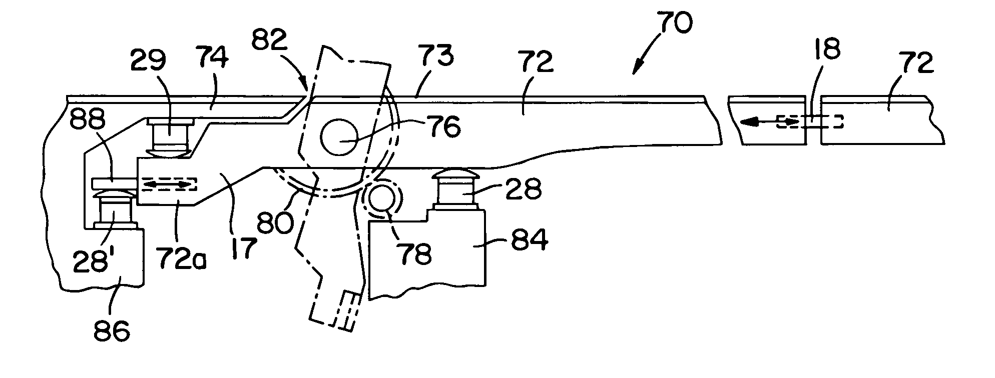
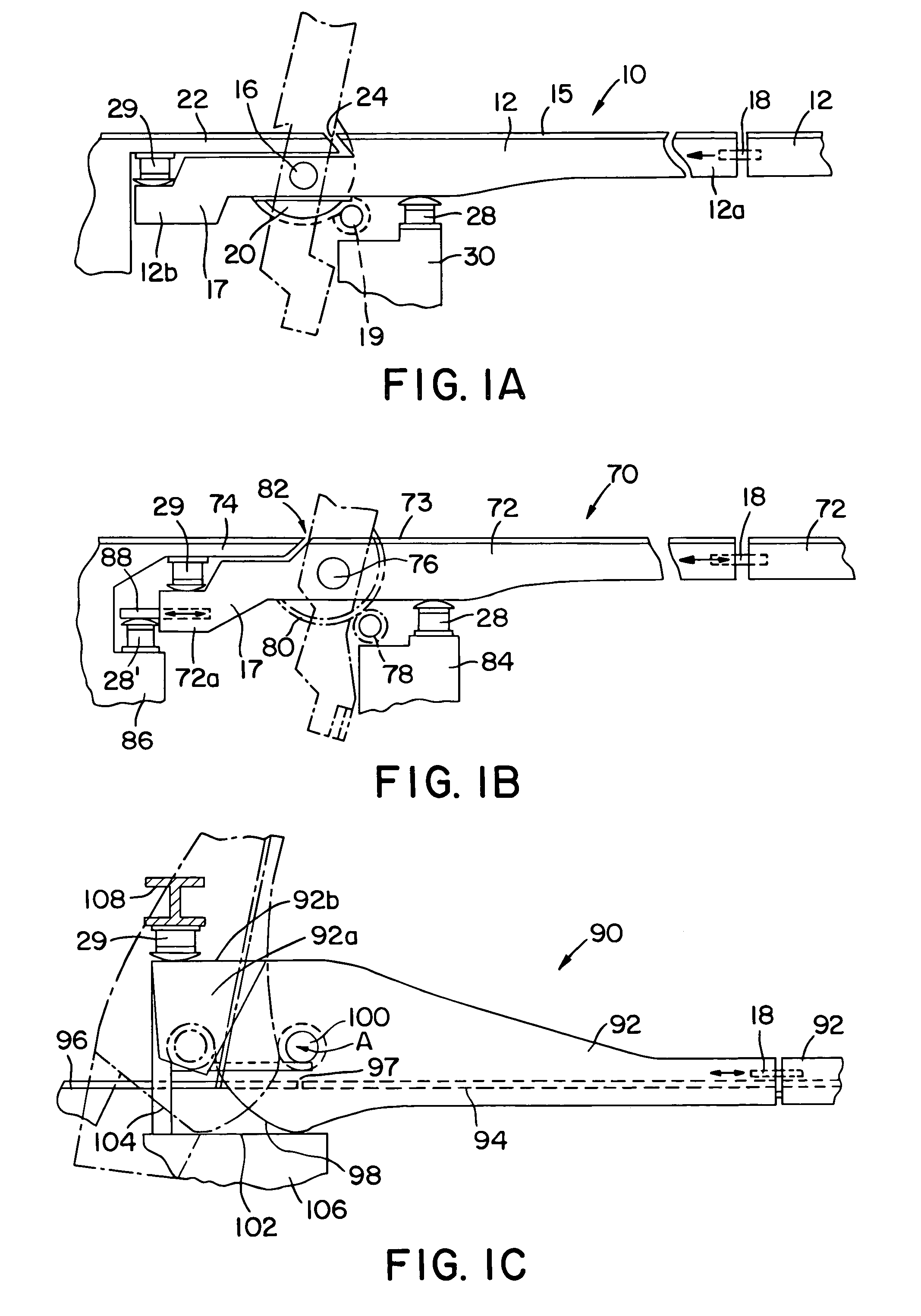
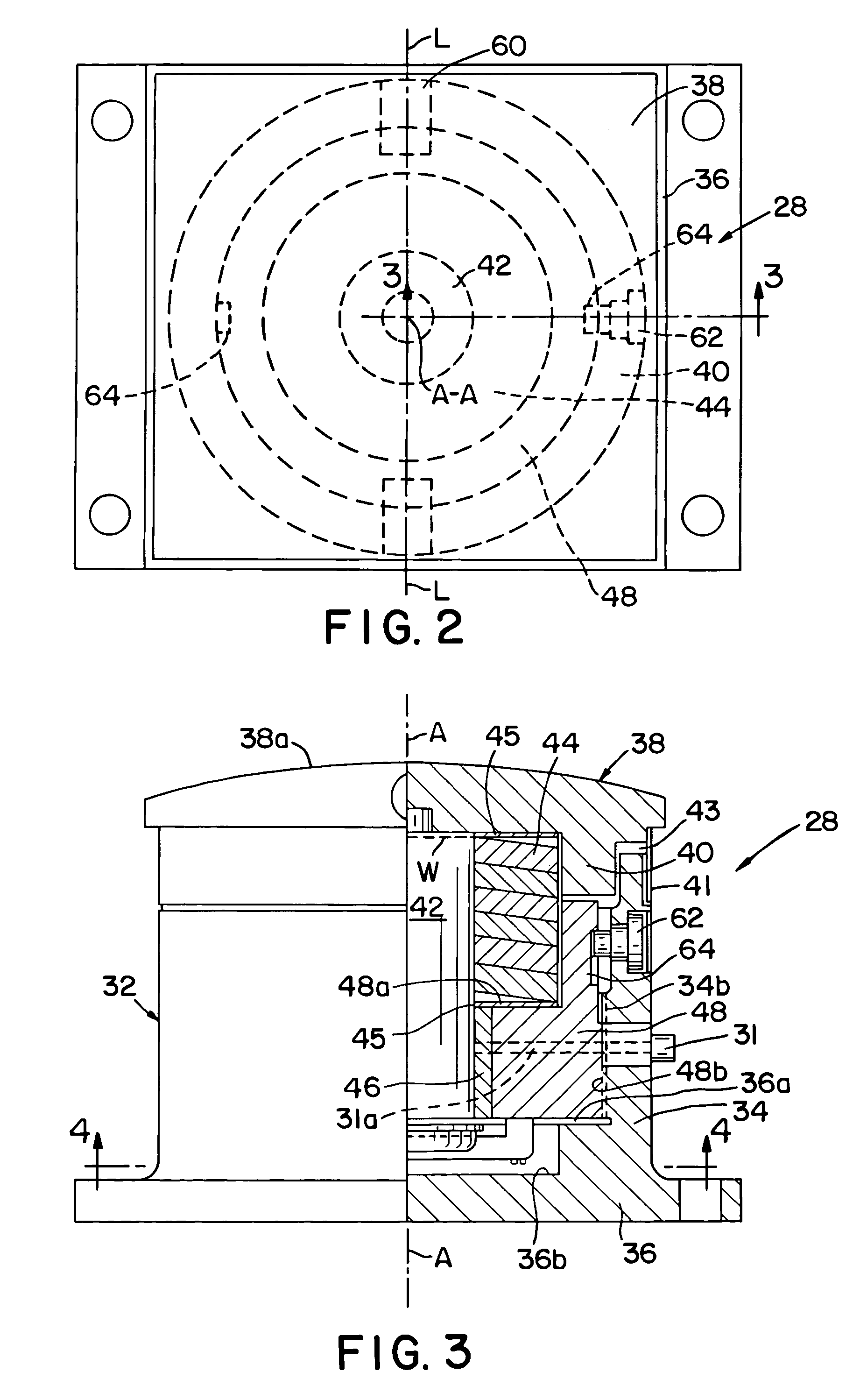
[0019]Referring now to the drawings, wherein like reference numerals and characters denote like or corresponding parts throughout the several views, FIG. 1A illustrates one embodiment of the invention incorporated in a trunnion bascule bridge 10 having a pair of opposed complementary span sections or leafs 10a and 10b. Each leaf, such as the leaf 10a, pivots about a trunnion 16 supported in a bearing (not shown) mounted on a fixed pier (not shown). The leafs 10a and 10b are similar in construction and include at least two girders 12 extending the full length of the movable span. Each girder has a forward leaf span portion 12a and a reward leaf tail portion 12b. A road bed surface 15 for vehicular traffic is supported by the leaf girders 12 on its forward span extension over a waterway below the bridge. A counterweight 17 is attached to rearward leaf tail portions 12b of girders 12 so that the movable leaf 10a is essentially balanced about a horizontal pivot axis extending through th...


PUM


Abstract

An adjustable static stabilizer used to ameliorate shock loading. The static stabilizer has a housing forming a chamber and an upwardly-open cylindrical carrier moveably mounted in the chamber. A plurality of spring washers are mounted in the carrier, and a shoe cap extends transverse to the carrier for engaging the spring washers therein. A tie rod interconnects the shoe cap and the carrier for displacement of the shoe cap relative to the housing, and a threaded means is disposed between the housing and the carrier for rotatably mounting the carrier in the housing which is operable upon rotation of the shoe cap relative to the housing to enable the overall height of the stabilizer to be adjusted.

Description

FIELD OF THE INVENTION[0001]The present invention relates generally to bridges, and more particularly, the present invention relates to apparatus for reducing impact loads to movable bascule bridge leafs and associated support structures as the leafs close as well as for maintaining static stability of the leafs when fully closed.BACKGROUND OF THE INVENTION[0002]Bascule bridges need to possess the ability for the bridge operator to quickly and reliably change span orientation to alternately permit the passage of land and waterway traffic. Bascule bridges must be able to open and close on demand; yet, at the same time they should be as rigid in their closed position as a fixed span. The system intended to secure bridge leafs in the closed position is customarily known as a “Static Stabilizing System” and it normally includes components such as span locks, live load shoes, anchorages, machinery brakes and, in some instances, tail locks. Live load shoes and anchorages are the heart of ...

Claims


Application Information

Patent Timeline
Patent Type & Authority Patents(United States)
IPC IPC(8): E01D15/06
CPCE01D15/06
Inventor CRAGG, ROBERT L.
Owner STEWARD MACHINE
Why Eureka
Try Eureka