Sliding revolving door

a sliding and revolving door technology, applied in the field of revolving doors, can solve problems such as draught and draught problems

Inactive Publication Date: 2006-04-04
BOON EDAM
View PDF14 Cites 8 Cited by
  • Summary
  • Abstract
  • Description
  • Claims
  • Application Information

AI Technical Summary

Benefits of technology

[0011]A second preferred embodiment of the revolving door according to the invention is characterized in that in a start-up phase when the door leaves rotate, and the sliding door begins to close off the entrance or exit, respectively, the sliding door will move more slowly than the end of the door leaf that is located near the sliding door and between its lateral edges, and in that in a closing phase, which succeeds the start-up phase and in which the sliding door completely closes off the entrance or exit, respectively, said sliding door will move faster than the end of the door leaf, until the end of the door leaf and the lagging lateral edge of the sliding door are close together, and the door leaf and the sliding door synchronously move on or stand still, until the start-up phase starts anew. The advantage with this embodiment is that it has a larger capacity for passing through compared with the above-mentioned first preferred embodiment so that a larger number of people are able to use the revolving door within a certain time unit. Those interested in technology will find the intriguing concerted action between the door leaves and the sliding door especially inspiring.

Problems solved by technology

Since there is no barrier of any kind between the entrance and exit when the door leaves are in a particular position there is a problem of draught, unless further measures are taken.
The rotation of the door leaves creates an open communication between the entrance and the exit of the prior art revolving door, giving rise to draught problems.

Method used


Image

  • Sliding revolving door
  • Sliding revolving door
  • Sliding revolving door

Examples


Embodiment Construction

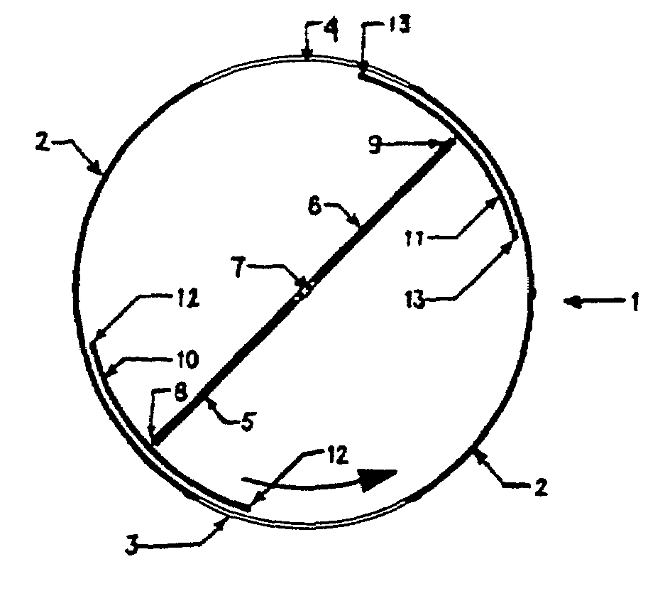
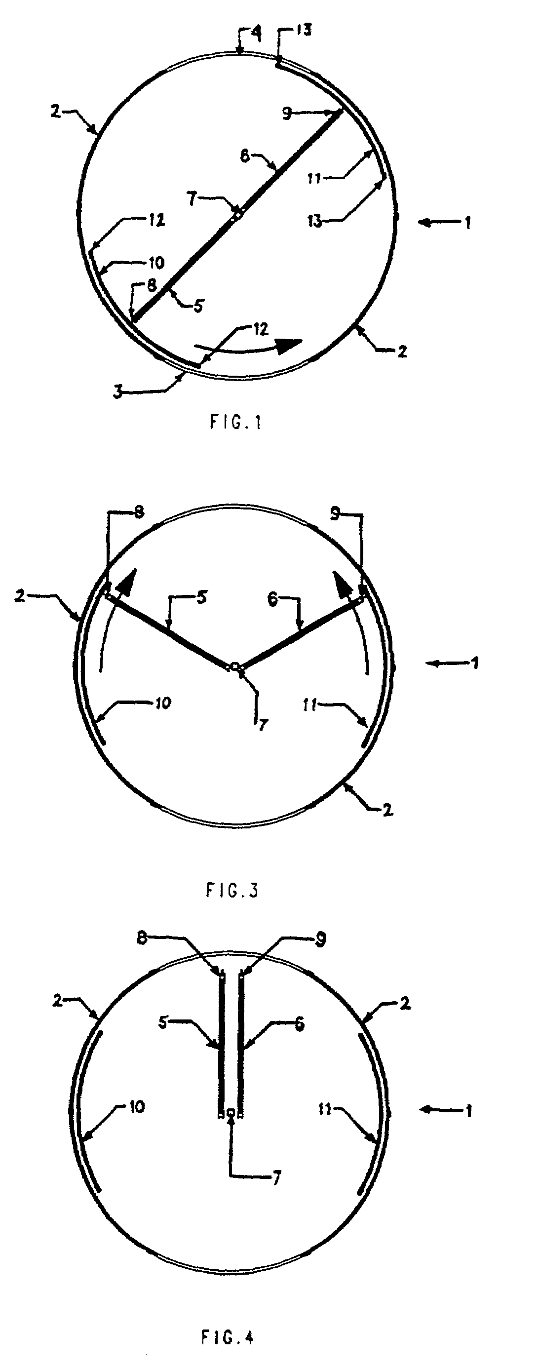
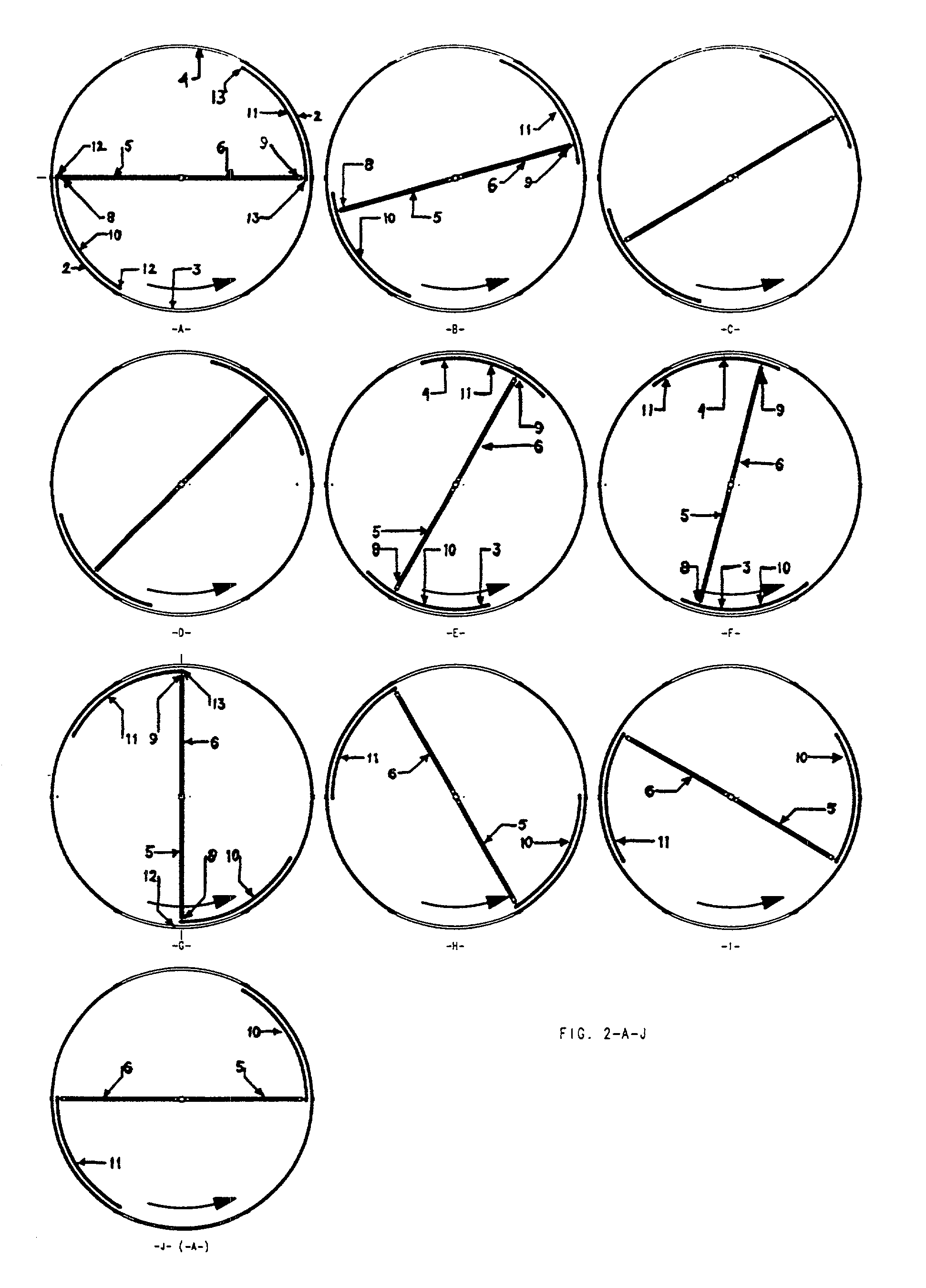
[0020]Referring now first to FIG. 1, where the revolving door according to the invention is indicated by reference number 1, and which is embodied with an at least partly cylindrical shell wall 2, which is provided with an entrance 3 and an exit 4. Such a revolving door 1 may be provided, for example, in the facade of a building or inside a building for the separation of different rooms that are in communication via the revolving door. Inside the shell wall 2, the revolving door 1 further comprises two rotating door leaves 5 and 6, which during normal operation are placed in each other's extended direction. Normal operation entails that the door leaves 5 and 6 in said position where the door leaves 5 and 6 lie in each other's extended direction, are able to stand still or to rotate about a central column 7. According to the invention, the revolving door 1 is now embodied such that a sliding door 10, 11 is provided between the shell wall 2 and an end 8 or 9, respectively, of at least...


PUM


Abstract

A revolving door comprising an at least partly cylindrical shell wall, which has an entrance and an exit, and two rotating door leaves, which during normal operation are in place extended in the opposite direction of each other inside the shell wall. Between the shell wall and an end of at least one door leaf, which end can move near and along the shell wall, a sliding door is provided, which is suitable for closing off the entrance or exit, respectively, and during normal operation the end of the door leaf is constantly positioned near the sliding door and between its lateral edges.

Description

CROSS-REFERENCE TO RELATED APPLICATIONS[0001]This application is continuation application of International Patent Application Serial No. PCT / NL01 / 00568, entitled “Revolving Door” to Rene Cornelis Nat, having an international filing date of Jul. 23, 2001, and claiming priority to Netherlands Patent Application Serial No. 1015852, having a filing date of Aug. 1, 2000, and the specifications thereof are incorporated herein by reference.BACKGROUND OF THE INVENTION[0002]1. Field of the Invention[0003]The invention comprises a revolving door comprising an at least partly cylindrical shell wall, including an entrance and an exit, and including two rotating door leaves which during normal operation are fully and oppositely extended inside the shell wall. Between the shell wall and an end of at least one door leaf, which end can move near and along the shell wall, a sliding door is provided, which is suitable for closing off either the entrance or exit, and during normal operation the end of...

Claims


Application Information

Patent Timeline
Patent Type & Authority Patents(United States)
IPC IPC(8): E05D15/02E06B3/90
CPCE06B3/906E06B3/90
Inventor NAT, RENE CORNELIS
Owner BOON EDAM
Why Eureka
Try Eureka