Heat shield arrangement for a hot-gas conducting component, in particular for structural pieces of gas turbines and method for production of said arrangement

Inactive Publication Date: 2006-04-04
SIEMENS AG
View PDF13 Cites 18 Cited by
  • Summary
  • Abstract
  • Description
  • Claims
  • Application Information

AI Technical Summary

Benefits of technology

[0010]The object of the invention is accordingly to disclose a heat shield arrangement for a hot-gas conducting structure, in particular a metal component of a gas turbine unit or combustion chamber, with heat shield elements anchored adjacently on

Problems solved by technology

A disadvantage of this is that hot gas from the combustion chamber can pass through the above-mentioned gaps and make contact with the support structure with the result that the material of the support structure can be damaged by the resulting massive heat impact.
A disadvantage of said arrangement is, for example, that a heat shield element with this type of arrangement cannot be installed or released independently of its adjacent heat shield elements.
If, for instance, only the anchorage of one heat shield element were released when said arrangement was being released,

Method used


Image

  • Heat shield arrangement for a hot-gas conducting component, in particular for structural pieces of gas turbines and method for production of said arrangement
  • Heat shield arrangement for a hot-gas conducting component, in particular for structural pieces of gas turbines and method for production of said arrangement
  • Heat shield arrangement for a hot-gas conducting component, in particular for structural pieces of gas turbines and method for production of said arrangement

Examples


Embodiment Construction

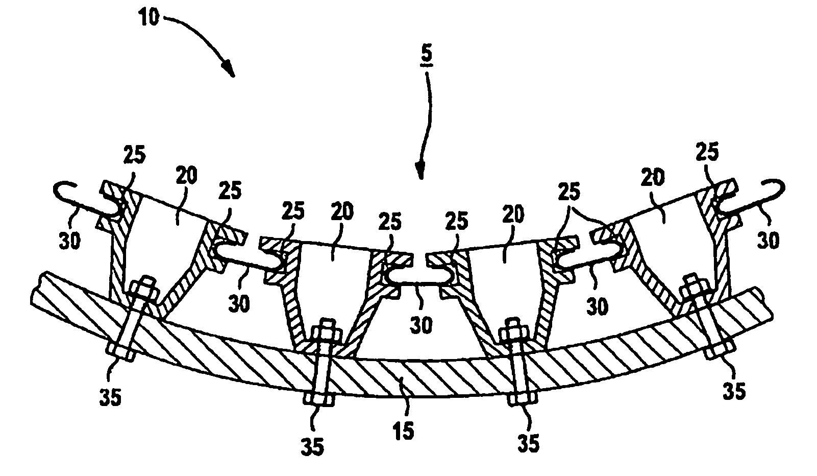
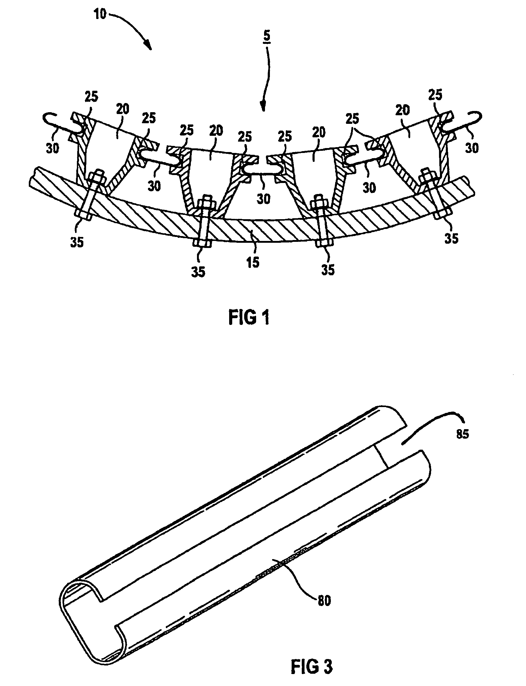
[0030]FIG. 1 shows a heat shield arrangement 5 according to the invention.

[0031]The heat shield arrangement 5 protects a support structure 15 from the destructive effect of hot gas formed in a combustion chamber 10.

[0032]The heat shield arrangement 5 comprises heat shield elements 20 arranged adjacently on the support structure 15 to cover a surface and anchored to this support structure 15 by means of securing elements 35, for example screw connections.

[0033]Between the individual heat shield elements 20 there is in each case a gap through which the hot gas formed in the combustion chamber could penetrate and attack the support structure 15. Because of the thermal expansion of the heat shields and also in order to allow easy serviceability, it is not possible to dispense with a gap.

[0034]The above described gaps between the heat shield elements 20 are sealed by means of seal elements 30 in order to protect the support structure 15 from being damaged or destroyed.

[0035]The heat shie...


PUM


Abstract

The invention relates to a heat shield arrangement for a hot gas conducting structure, in particular a metal component of a gas turbine unit or combustion chamber, with the heat shield elements anchored adjacently on a support structure to cover a surface. Said heat shield elements each comprise a lateral groove, arranged in the region of the edge of the surface thereof facing the hot gas, at least two adjacent shield elements are connected by at least one seal element mounted in the groove. The seal element is embodied as a sealing flap, which may be displaced from a first position to a second position and vice versa, whereby the first position is an open position without a sealing effect and the second position is a closed position with a sealing effect. According to said method the sealing flap is moved from the first to the second position by the movement of a heat shield element.

Description

[0001]This application is a continuation of International Application No. PCT / EP02 / 05578, filed May 21,2002 and claims the benefit thereof. The International Application claims the benefits of European application No. 01112710.7 filed May 25, 2001, both applications are incorporated by reference herein in their entirety.FIELD OF INVENTION[0002]The invention relates to a heat shield arrangement for a hot-gas conducting component, in particular for structural parts of gas turbines. It further relates to a method for producing said arrangement.BACKGROUND OF INVENTION[0003]The arrangement contains a plurality of heat shield elements disposed adjacently on a support structure and anchored to this to cover a surface, and wherein at least two adjacent heat shield elements each have at least one lateral groove, arranged in the region of the edge of the surface thereof facing the hot gas, these heat shield elements being connected by means of at least one seal element installed in the groove...

Claims


Application Information

Patent Timeline
IPC IPC(8): F02C3/00F02C7/28F23R3/42F02C7/24F23M5/00F23R3/00F27D1/00F27D1/04F27D1/14F27D99/00
CPCF23M5/00F23R3/002F27D1/0003F23M2900/05005F27D99/0073F27D1/04F27D1/145F23R2900/00012
Inventor TIEMANN, PETER
Owner SIEMENS AG
Why Eureka
Try Eureka