Variable valve

a variable valve and valve body technology, applied in the direction of combustion-air/fuel-air treatment, machines/engines, fuel air intakes, etc., can solve the problems of numerous limitations and disadvantages of the known barrel valve system

Inactive Publication Date: 2006-04-04
VARIABLE VALVE TECH
View PDF7 Cites 7 Cited by
  • Summary
  • Abstract
  • Description
  • Claims
  • Application Information

AI Technical Summary

Benefits of technology

[0006]The present invention is for variable area which employs at least two barrels which are parallel to one another and rotate in synchronization with one another. The barrels contain openings perpendicular to their rotational axes which mate at the interface of the barrels so that they can create an opening perpendicular to the barrels which is concentric with a port in a manifold or valve body. The openings in each barrel provide an opening of a desired size at an open position and a predetermined minimum size at a closed position. The closed position can also be a completely closed position to cut off flow entirely. Once benefit of the invention is that the openings in the barrel may be sized so that they can match non-circular manifold openings.
[0007]A further benefit of the present invention is that the openings can be sized and the gearing between barrels chosen, so that the intake area at intermediate settings is a nonlinear function of control setting applied to the barrel valves. In this way, tuning of the system can be varied to obtain a desired response.
[0014]From the above, it may be seen that the present invention provides a means of configuring intake systems for intake combustion engines which have important advantages over butterfly valves. For example, the intake valve system may be configured for a non-circular opening at a wide open throttle, thereby being more easily mated to multi valve cylinder heads, which often do not have circular intake ports. Also, since the apertures in the cylinders may be easily varied in cross-section, it is possible to have different cross-section to rotation angles to tune the intake system as a function of throttle opening.

Problems solved by technology

Because of their long use and development, butterfly intake valves have been developed which adequately address those issues, but many non-butterfly systems still present problems in partial throttle situations.
However, known barrel valve systems have numerous limitations and disadvantages compared to butterfly systems at partial throttle openings.

Method used


Image

  • Variable valve
  • Variable valve
  • Variable valve

Examples


Embodiment Construction

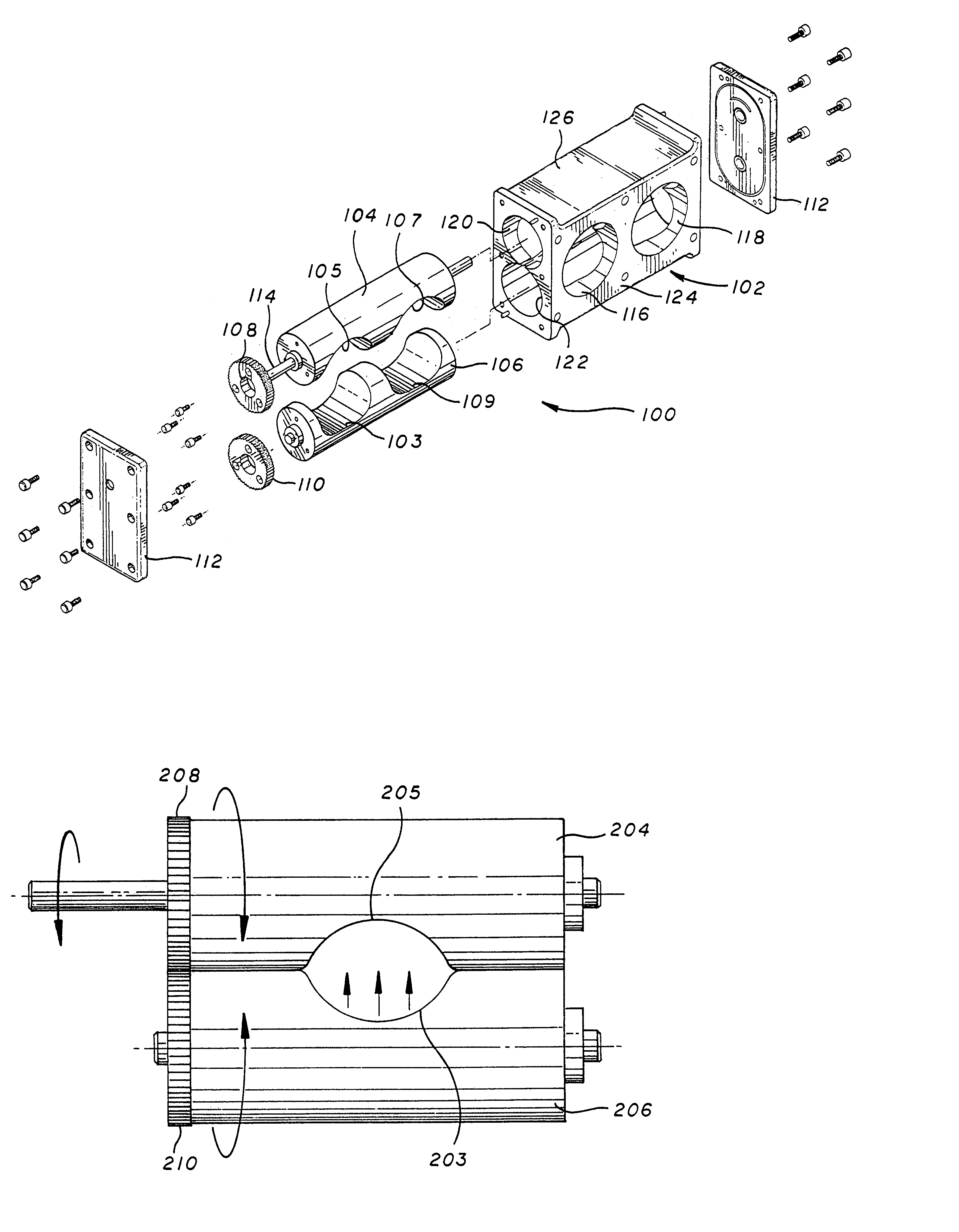
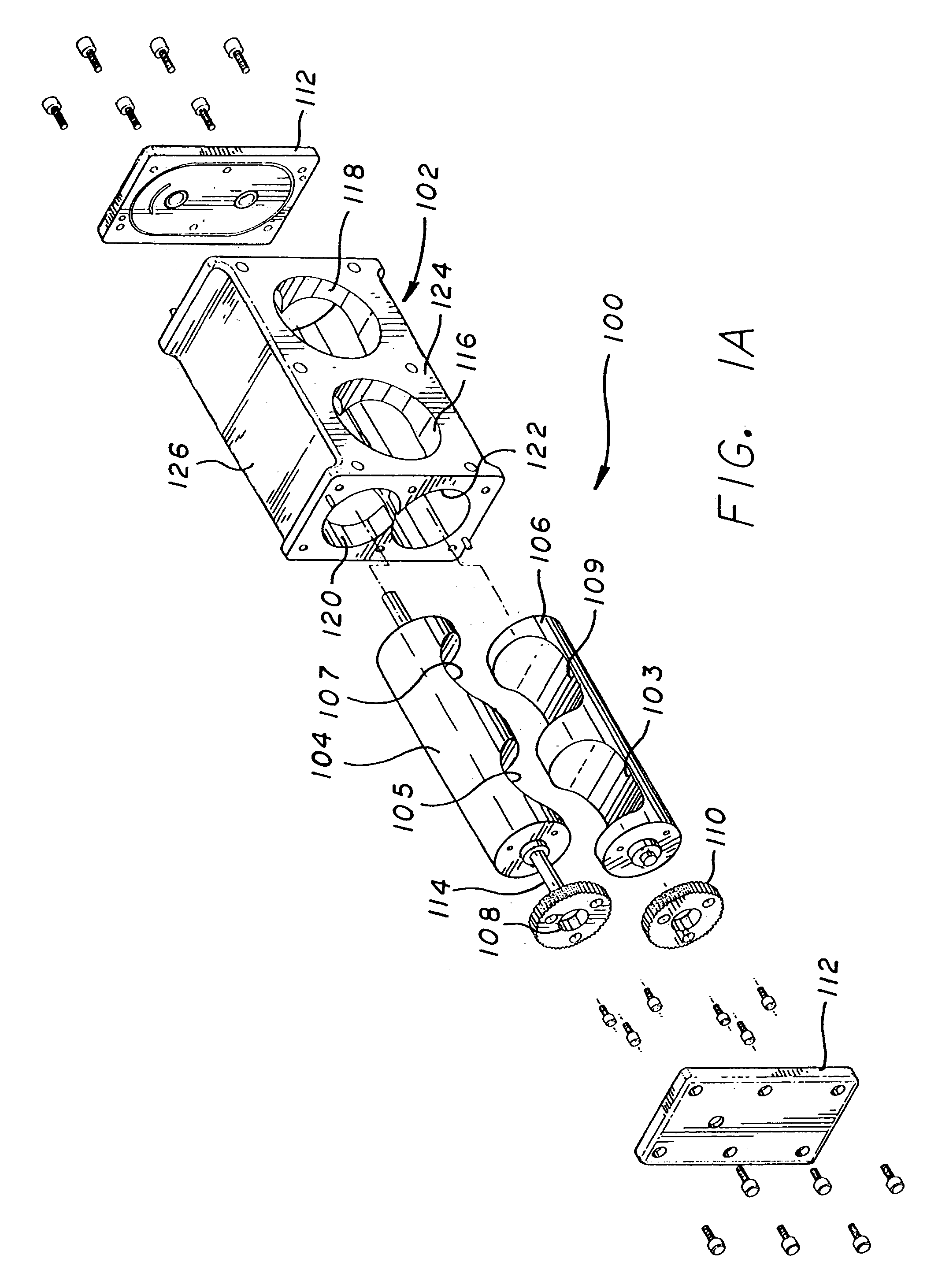
[0026]The present invention provides many benefits over prior art valve systems and may also be applied to other non-engine applications in which it is desirable to have a robust variable opening valve. While the invention will be described in a presently preferred embodiment in which the opening in the valve in a fully open position has a circular cross-section, the valve may be configured to have a non-circular cross section at a wide open position for various applications. Similarly, while the embodiments which are described illustrate a fully closed position and direct one to one gearing, both the gearing and the cylinder cross section may be changed to provide different minimum throttle openings and slopes of area vs. throttle inputs as desired.

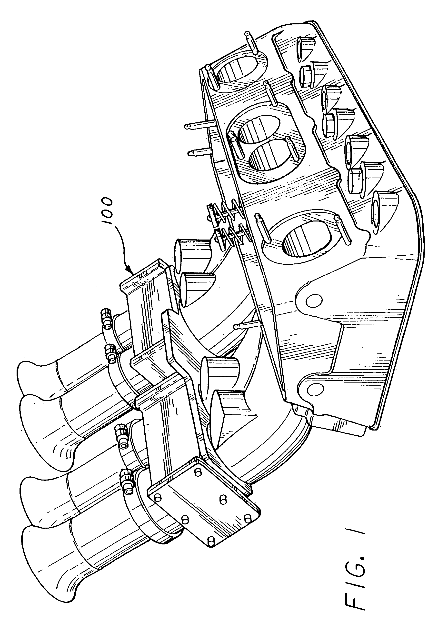
[0027]Reference will now be made to preferred and alternative embodiments of the invention, examples of which are illustrated in the accompanying drawings. While the invention will be described in conjunction with the preferred embodimen...


PUM


Abstract

A variable valve comprising a first cylinder having an aperture and a second cylinder having a second aperture. The first cylinder moves between a first position and a second position. Preferably, the second cylinder moves in cooperation with the first cylinder such that the first aperture and the second aperture form a variable sized opening when the first cylinder moves from the first position toward the second position. The first aperture and the second aperture preferably rotate. The variable sized opening is preferably in a closed position when in the first position. The valve comprises a block body including a passage for allowing air to pass therethrough. The first cylinder and the second cylinder are coupled to the block body and configured in a predetermined position such that the variable sized opening is in communication with the passage. The valve also includes an axle for driving the first cylinder and the second cylinder.

Description

[0001]This application is a Continuation-In-Part Application, which claims priority from U.S. application Ser. No. 10 / 348,357, filed 21 Jan. 2003, issued on 30 Mar. 2004 as U.S. Pat. No. 6,712,040, entitled VARIABLE THROTTLE VALVE, which is incorporated herein by reference.BACKGROUND OF THE INVENTION[0002]1. Field of the Invention[0003]The present invention relates to an apparatus for regulating flow through a passage. More particularly, the present invention relates to a rotary valve.[0004]2. Description of Related Art[0005]Spark ignition internal combustion engines often employ a butterfly valve in a throttle valve assembly to control air intake. While a butterfly valve works adequately, the horsepower can be increased if the valve employed in the throttle assembly is less restrictive, since the butterfly valve shaft and the plate remain in the airflow path, obstructing airflow while in open throttle. In the past, slide throttles, pivoting variable intakes and other means have bee...

Claims


Application Information

Patent Timeline
Patent Type & Authority Patents(United States)
IPC IPC(8): F02D9/08
CPCF02D9/08
Inventor GIFFIN, JOHN
Owner VARIABLE VALVE TECH
Why Eureka
Try Eureka