Automated cleansing sprayer having separate cleanser and air vent paths from bottle

a technology of automatic cleaning sprayer and cleaning fluid, which is applied in the direction of dispenser, liquid transfer device, transportation and packaging, etc., can solve the problems of no scrub” cleaning fluid to work well, wall and door, undesirable task, etc., to facilitate the flow of fluid, improve the control of cleaning fluid delivery, and avoid excessive air addition

Active Publication Date: 2006-04-04
SC JOHNSON & SON INC
View PDF86 Cites 100 Cited by
  • Summary
  • Abstract
  • Description
  • Claims
  • Application Information

AI Technical Summary

Benefits of technology

[0015]The piercing post includes a cleanser conduit in fluid communication with the well for delivering cleanser to the well, and an air vent path separate from the cleanser conduit for venting the bottle. In one configuration of the sprayer, the air vent path is in fluid communication with a vent outlet of the well. In another configuration of the sprayer, the air vent path is in communication with an air passage between the bottle and an inner surface of the well. In one form, the cleanser conduit terminates at an opening of the piercing post, and the air vent path terminates at another opening of the piercing post such that the opening of the air vent path is at a position further into the bottle than the opening of the cleanser conduit when the bottle is installed in the inverted orientation in the tray. A wall may also extend outward from the piercing post between the opening of the air vent path and the opening of the cleanser conduit. Optionally, a gasket may be used to seal against the piercing post and limit leakage around the piercing post when the bottle is installed in the inverted orientation in the tray.
[0022]The invention facilitates the flow of fluid from the bottle (for example by overcoming any negative pressure effect in the bottle), and does so in a manner that avoids excessive air being added in a way that causes frothing or foaming in the fluid in the bottle. Thus, the problem of negative pressure build-up in the bottle, or uncontrolled air venting, is addressed by the present invention. The invention also provides for improved control of cleaning fluid delivery from the dispenser, by way of, among other things, the cleanser conduit in the piercing post and the valve. Additionally, uncontrolled mixing of the air flow into the liquid flow is avoided, thereby improving dispensing of the cleaning fluid.

Problems solved by technology

The walls and doors of shower / bathing enclosures can become mildewed, coated with soap build up or hard water and mineral deposits, or become otherwise soiled, during typical use.
Removing these deposits and stains normally requires one to scrub the walls and doors by hand, which is an undesirable task.
However, for these “no scrub” cleaners to work well they preferably should be applied immediately after the shower has been used.
This requires a consumer to keep a pump spray bottle of the cleanser in or near the shower enclosure (further cluttering the shower area), that the consumer remember to do the spraying (which may be problematic if the consumer has just woken up), and that the consumer be willing to spend the time to spray the enclosure (for example they may be running late in the morning).
A drawback with this system is that the user must manually turn on the supply water (if not already on), adjust the diverter, squeeze cleanser into the sprayer and shut off the water after the walls have been washed.
There is also some risk that the consumer will be sprayed with the cleanser.
Thus, it is not something that a consumer can easily and inexpensively retrofit to their shower enclosure.
Again, this system is not suitable for easy and inexpensive retrofitting.
However, the use inverted bottles in such a dispenser can present problems.
For example, negative pressure (i.e., vacuum) effects in the bottle may hinder the flow of fluid from the bottle.
For instance, too much air flow into the bottle can cause frothing or foaming of the liquid in the bottle, whereas inadequate air flow into the bottle fails to overcome the negative pressure effects.
Additionally, mixing of the air flow into the liquid flow must be controlled as certain levels of mixing of the air flow into the liquid flow may prevent appropriate dispensing of the liquid.

Method used


Image

  • Automated cleansing sprayer having separate cleanser and air vent paths from bottle
  • Automated cleansing sprayer having separate cleanser and air vent paths from bottle
  • Automated cleansing sprayer having separate cleanser and air vent paths from bottle

Examples


Embodiment Construction

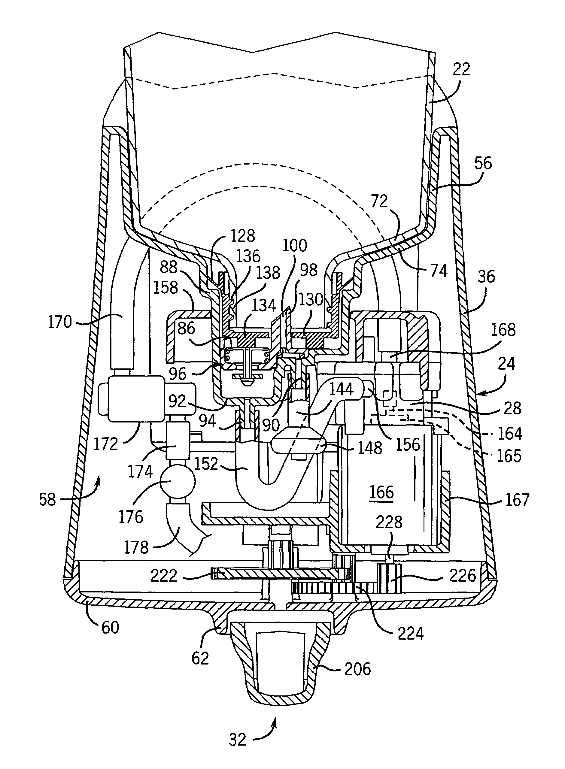
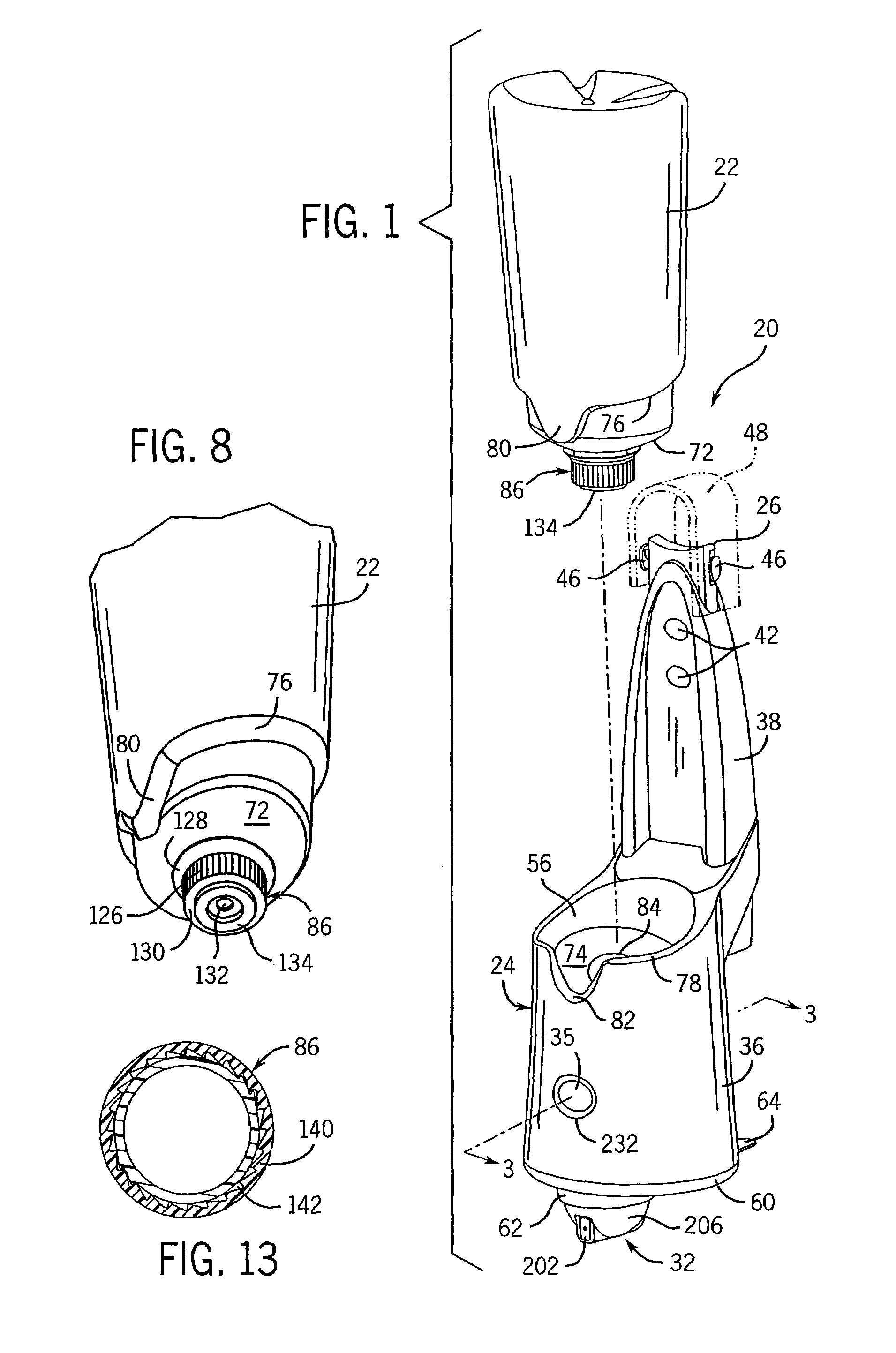
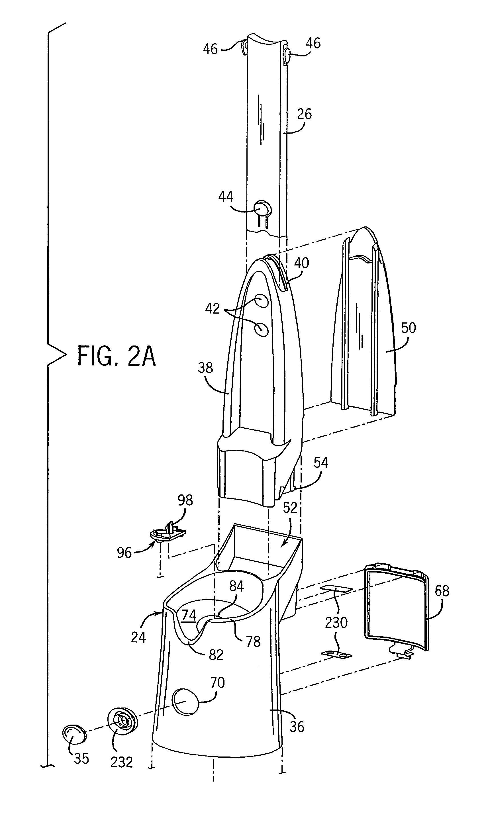
[0063]As background, we describe an earlier prototype of an automated sprayer generally referred to in the figures by reference number 20. With particular reference to FIGS. 1–2B, the sprayer 20 includes as main components a bottle 22, a housing 24 with an adjustable hanger 26, a pump 28, a drive mechanism 30, a spray head 32 and a control circuit 34. The sprayer is typically suspended via the hanger from a shower spout or the like and then activated via a button 35 at the front of the sprayer to rotate a spray head and pump cleanser from the bottle out of the spray head during a spray cycle of a prescribed time period, after which dispensing is automatically terminated.

[0064]The exterior of the sprayer is defined by the housing 24, which can be molded from, for example, plastic by any suitable technique and consists primarily of two pieces, a receptacle 36 and a hanger tower 38 that easily snaps into a pocket in the receptacle. This allows the sprayer to be shipped and stored in a ...


PUM


Abstract

An automated sprayer for spraying the walls of a shower enclosure with a liquid cleanser dispenses the cleanser using a pump and rotatable spray head. A motor drives the pump and rotates the spray head. The sprayer has a showerhead mountable housing with a hanger. The housing supports a bottle of cleanser in an inverted fashion. Cleanser is delivered from the bottle through a cleanser conduit in the piercing post into a well of the housing. The bottle is vented from the well through an air vent path in the piercing post or from a well vent outlet through the air vent path in the piercing post. An outlet valve in the well permits outflow of cleanser from the well. Various bottle caps and bottle closures are also provided to improve venting and / or limit cleanser leakage from the bottle when the bottle is installed in the housing.

Description

CROSS-REFERENCE TO RELATED APPLICATIONS[0001]Not applicable.STATEMENT OF FEDERALLY SPONSORED RESEARCH OR DEVELOPMENT[0002]Not applicable.BACKGROUND OF THE INVENTION[0003]This invention relates to sprayers that are designed to automatically clean enclosures. It appears to be especially well suited for automatically cleaning shower / bathing enclosures of the type typically found in homes.[0004]The walls and doors of shower / bathing enclosures can become mildewed, coated with soap build up or hard water and mineral deposits, or become otherwise soiled, during typical use. Removing these deposits and stains normally requires one to scrub the walls and doors by hand, which is an undesirable task.[0005]To assist in this task, cleaning chemicals may be sprayed, squirted, or otherwise applied on the surfaces to be cleaned. After allowing the active ingredients some time to “work”, the walls are then wiped with a cloth, brush, or scrubbing pad, and then rinsed with water.[0006]In some cases th...

Claims


Application Information

Patent Timeline
Patent Type & Authority Patents(United States)
IPC IPC(8): B67D5/00B67D7/02A47K5/12B05B9/08B67D99/00
CPCA47K3/281A47K5/1202B05B9/0894B05B9/0403B05B9/0861B05B3/02B05B1/08
Inventor MAZOOJI, AMBER N. D.KOVARA, TERRY M.NEUMANN, PETER M.LEIFHEIT, DAVID H.ALLEN, MICHAEL W.BLANKENSHIP, PAUL M.PILLION, LAWRENCE M.
Owner SC JOHNSON & SON INC
Why Eureka
Try Eureka