
Connector allowing reduction in thickness of an apparatus to which the connector is to be mounted

Active Publication Date: 2006-04-04
JAPAN AVIATION ELECTRONICS IND LTD
View PDF19 Cites 28 Cited by
  • Summary
  • Abstract
  • Description
  • Claims
  • Application Information

AI Technical Summary

Benefits of technology

[0005]It is therefore an object of the present invention to provide a connector which allows the reduction in thickness of an apparatus to which the connector is to be mounted.

Problems solved by technology

However, the connector disclosed in each of these publications is relatively large as compared with the electronic parts mounted to the electronic or electric apparatus and therefore inhibits the reduction in thickness of the electronic or electric apparatus.

Method used


Image

  • Connector allowing reduction in thickness of an apparatus to which the connector is to be mounted
  • Connector allowing reduction in thickness of an apparatus to which the connector is to be mounted
  • Connector allowing reduction in thickness of an apparatus to which the connector is to be mounted

Examples


Embodiment Construction

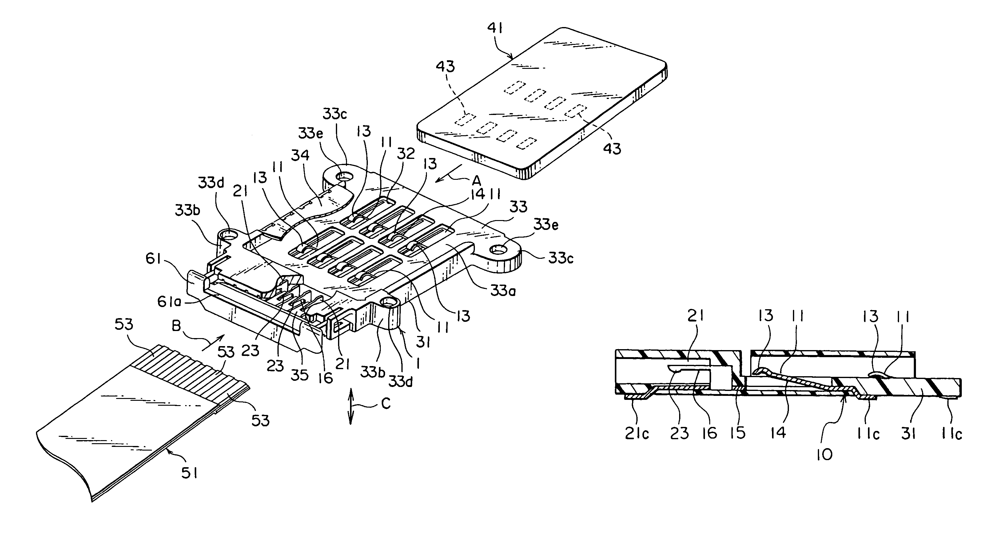
[0024]Referring to FIGS. 1 through 7, description will be made as regards a connector according to one embodiment of this invention.

[0025]The connector 1 illustrated in the figure is mounted to an apparatus, such as a mobile telephone and a mobile terminal and serves to connect a first connection object 41 of a flat shape, such as a SIM card, a MMC, a SD card, and a memory stick, to a second connection object 51 of a flat shape, such as a FPC (Flexible Printed Circuit) and a FFC (Flexible Flat Cable). The first connection object 41 has a plurality of first mating contacting portions 43 disposed on one surface thereof and arranged in two rows. The second connection object 51 has a plurality of second mating contacting portions 53 disposed at one end thereof and arranged in a single row. In the manner which will be described below, the connector 1 comprises plural or eight conductive members 10 and an insulator 31 coupling or holding the conductive members 10.

[0026]The insulator 31 ha...


PUM


Abstract

An insulator has a base surface extending along a flat plane, a first insert portion defined by the base surface and adapted to receive a first connection object therein in a first direction parallel to the base surface, and a second insert portion placed parallel to the first insert portion on the flat plane and adapted to receive a second connection object therein in a second direction which is parallel to the base surface and different from the first direction. The conductive member has a first contacting portion disposed over the base surface and adapted to be brought into contact with the first connection object in a third direction perpendicular to the flat plane, a second contacting portion disposed in the second insert portion and adapted to be brought into contact with the second connection object in the third direction, and a base plate portion connected to the first and the second contacting portions and fixedly held by the insulator.

Description

[0001]This application claims priority to prior Japanese application JP 2002-361234, the disclosure of which is incorporated herein by reference.BACKGROUND OF THE INVENTION[0002]This invention relates to a connector adapted to be mounted to an electronic or electric apparatus, such as a mobile telephone or a mobile terminal.[0003]Recently, a small-sized external memory device such as a SIM (Subscriber Identity Module) card, a MMC (MultiMedia Card), a SD (Secure Digital) card, and a memory stick is known and increasingly used. The external memory device of the type may be used with an electronic or electric apparatus, such as a mobile telephone and a mobile terminal, as a module for identification of a subscriber. Upon use, the external memory device is connected to the apparatus through a connector which is mounted to the electronic or electric apparatus together with various parts, such as electronic parts.[0004]The connector of the type is disclosed, for example, in JP 2000-260537...

Claims


Application Information

Patent Timeline
IPC IPC(8): H01R24/00G06K17/00H01R12/62H01R12/79H01R13/639
CPCH01R12/62
Inventor MATSUNAGA, AKIHIRO
Owner JAPAN AVIATION ELECTRONICS IND LTD
Features
  • Generate Ideas
  • Intellectual Property
  • Life Sciences
  • Materials
  • Tech Scout
  • Unparalleled Data Quality
  • Higher Quality Content
  • 60% Fewer Hallucinations
Learn More